


6. GUI orientation
6.9 Configuration Menu > System diagram area
General
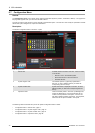
The system is represented graphically in this part of the S ystem configuration page. It is here that the user c an select a system (or
create a new one), or select a system element (inputs, outputs, destinations …)
Description
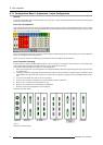
Devices and destinations that composed the system are graphically represented:
Image 6-9
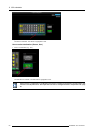
Diagram area
In this area, the rear panel of the selec ted system is represented graphically w ith the cards and the connectors ar e color coded to
indicate their status.
On the right hand s ide of the devices is a list of the created destinations (Screen and Auxiliary).
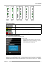
The tabs o n the top allow access to the different systems connected to the GUI. The last tab allows the users to create a new system.
A s et of zoom buttons allows to reduce or enlarge the view size. T his functionality is very useful when the system is composed of
more than one device.
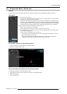
How to create new system
1. Click on the Add New System tab on the top.
A new empty tab is c reated.
2. Drop a device on this system. R efer to the pr ocedure to add a device in the section "Configuration Menu > Device area", page 77
3. Change the system name to avoid confusion when you control more than one system on the same Event Master Control Software.
Double click on the ta b, the tab background changes to a dar k blue color indicating that modifications can be made.
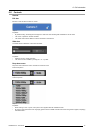
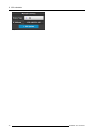
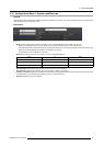
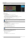
How to remove system
1. Click on the “X” button on the sy stem tab.
Image 6-10
Aconfirma tion window appears.
2. Click on OK.
The tab is remove.
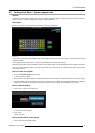
How to select device in the system
1. Click on the area below the E2 graphic.
R5905948 E2 12/12/2014
79