


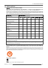
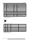
A. Specifications
DVI connector
Pin
Signal
4
T.M.D.S. Data 4-
16 Hot Plug D etect
5
T.M.D.S. D ata 4+
17
T.M.D.S. Data 0-
6
DDC Clock
18
T.M.D.S. Data 0+
7
DDC Data
19
T.M.D.S. Data 0/5 Shield
8
Analog Vertical Sync
20
T.M.D.S. Data 5-
9
T.M.D.S. Data 1-
21
T.M.D.S. Data 5+
10
T.M.D.S. D ata 1+
22
T.M.D.S. Clock Shield
11
T.M.D.S. Data 1/3 Shield
23
T.M.D.S. Clock +
12
T.M.D.S. Data 3-
24
T.M.D.S. Clock -
MicroCross Pins
Pin
Signal
Pin
Signal
C1
Analog Red Video
C4 Analog Horizontal S ync
C2 Analog Green Video C5 Analog Common Ground Return
C3
Analog Blue Video
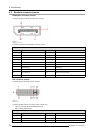
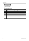
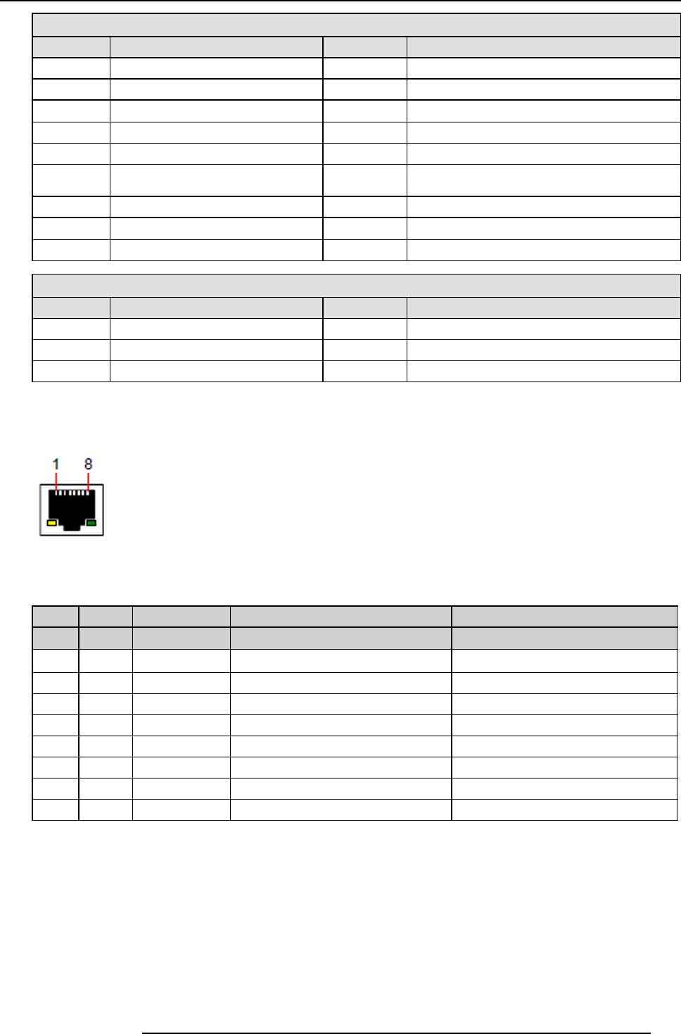
Ethernet connector pinouts
The following figure illustrates the Ethernet connector.
Image A-3
Ethernet connector
The following table lists Ethernet connector pinouts.
10/100 Base- T — RJ45 port 1000 Base-T — RJ45 port
Pin Pair Color Description Description
13
white/green
TXD+ TX0+
23
green
TXD- TX0-
32
white/orange
RXD+ RX0+
4 1 blue
—
TX1+
51
white/blue
—
TX1-
62
orange
RXD- RX0-
74
white/brown
—
Rx1+
8 4 brown
—
RX1-
HDMIconnector pinouts
The following figure illustrates the HDMI connector.
R5905948 E2 12/12/2014
289