


A. Specifications
A.2 Standard connector pinouts
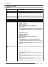
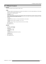
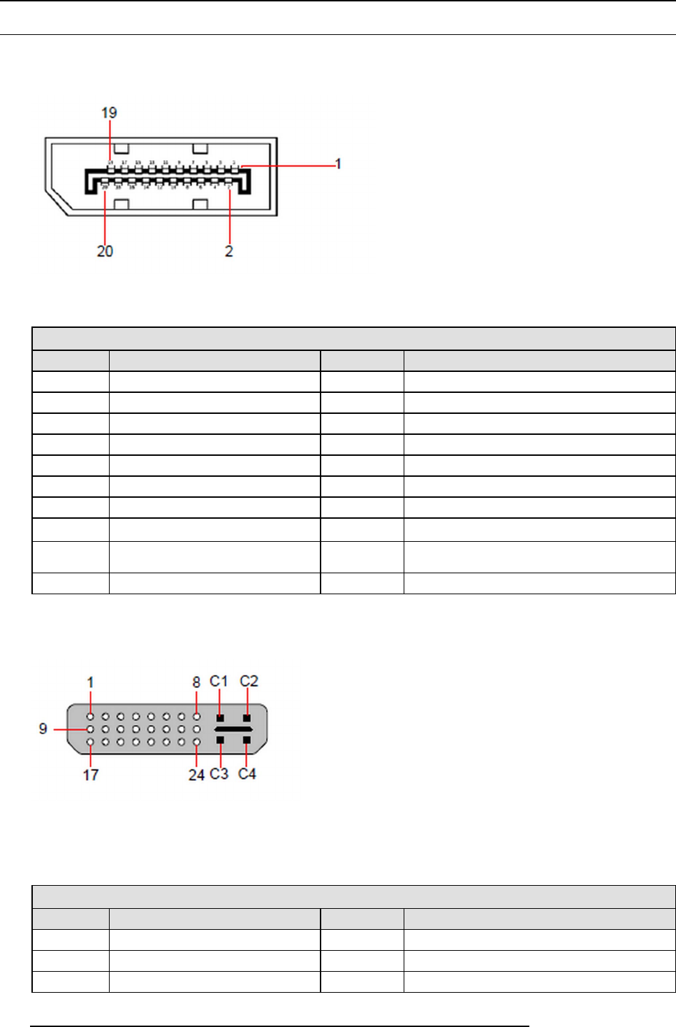
DisplayPort connector pinouts
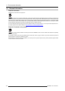
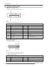
The following figure illustrates the DisplayPort connector.
Image A-1
DisplayPort connector
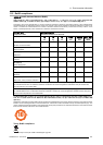
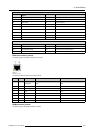
The following table lists the DisplayPort connector pinouts.
DisplayPort connector
Pin
Signal
Pin
Signal
1
ML_Lane 0 (p)
11
GND
2
GND
12
ML-Lane 3 (n)
3
ML_Lane 0 (n)
13
CONFIG1 (connected to Ground)
4
ML-Lane 1 (p)
14
Config2 (connected to Ground)
5
GND
15
AUX CH (p)
6
ML_Lane 1 (n)
16
GND
7
ML-Lane 2 (p)
17
AUX CH (n)
8
GND
18 Hot Plug D etect
9
ML_Lane 2 (n)
19
Retu rn (return for power)
10 ML_Lane 3 (p) 20 DP_PWR Power for connector (3.3 V, 500 mA)
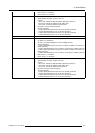
DVI c onnector pinouts
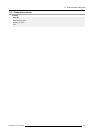
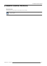
The following figure illustrates the DVI connector.
Image A-2
DVI connector
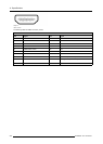
The following tables lists DVI Connector pinouts. Please note:
• T.M.D.S = Transition M inimized Differential S ignal
• DDC = Display Data Channel
DVI connector
Pin
Signal
1
T.M.D.S. Data 2-
13
T.M.D.S. Data 3+
2
T.M.D.S. D ata 2+
14 +5V Power
3
T.M.D.S. Data 2/4 Shield
15
ground (for +5V)
288 R5905948 E2 12/12/2014