


4. Hardware orientation
4.2 Rear panel
About rear panel
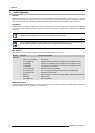
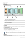
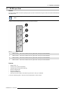
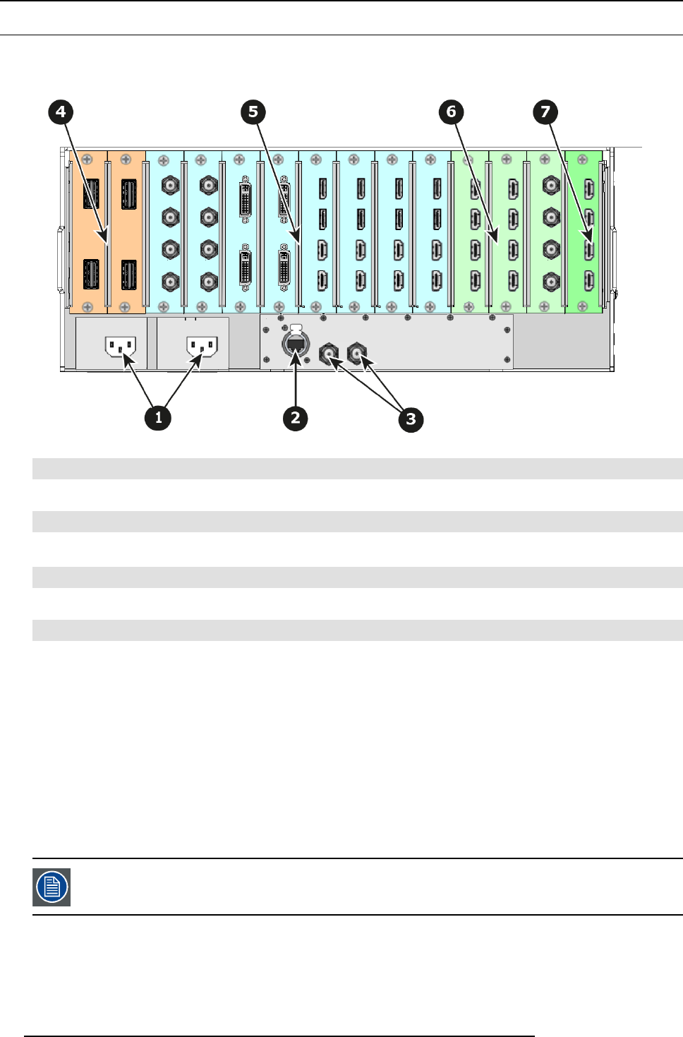
The figure below illustrates the E2 rear panel.
Image 4-4
1
Two AC connectors
2
RJ-45 connector for 10/100 BaseT Ethernet comm unications
3 Two G enloc k Input BN C with passive Loop-through
4 Two Expansion link cards
5
Eight Input cards (HDMI/DP, S DI, DVI)
6
Three Outputs cards ( DVI, SDI)
7
One Multiviewer card (HDMI)
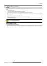
AC connectors
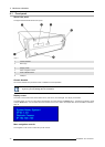
E2 is equipped with two redundant power supplies. During normal operation the load is s hared equally by both supplies. If one
supply fails, the sec ond carries the whole load. Two AC Connector a re provided to connect the E2 to your facility’s A C power source
through the supplied power cor ds
.
Input Power Specification: 100-240 VAC, 47-63 Hz
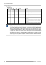
On each powe r supply there are 3 LED lights that provide status information as follows:
• DC Output Power LED: when Green, t
he supply is outputting valid DC power.
• Status LED: when amber indicates that an error has occurred.
• AC Input Power LED: when green it indicates that the supply is connected to a valid AC power.
Therefore, during nor mal operating conditions, the input AC and O utput DC LEDs will turn green.
Note that the power supplies a re installed upside down, so the silkscreen markings will also appear upside
dow n.
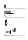
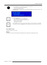
Ethernet port
One RJ-45 connector is provided for 10/100Bas eT E thernet c omm unications with the E2. The port is used for runn ing the Web
Interface an d for co nnection to an external device.
32
R5905948 E2 12/12/2014