


Getting Started Teledyne API – Model T300/T300M CO Analyzer
68
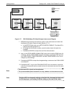
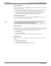
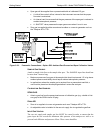
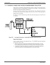
Span gas will be supplied from a pressurized bottle of calibrated CO gas.
A critical flow control orifice, internal to the instrument ensures that the proper
flow rate is maintained.
An internal vent line ensures that the gas pressure of the span gas is reduced to
ambient atmospheric pressure.
A SHUTOFF valve preserves the span gas source when it is not in use.
Zero gas is supplied by either an external scrubber or a zero air generator such as
the Teledyne API’s T701.
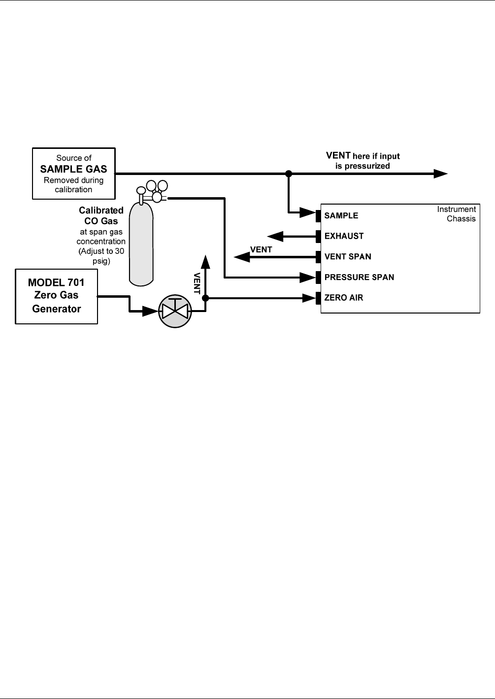
Figure 3-23: Pneumatic Connections – Option 50B: Ambient Zero/Pressurized Span Calibration Valves
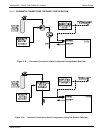
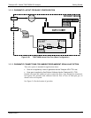
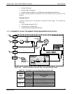
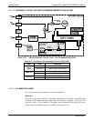
SAMPLE GAS SOURCE
Attach a sample inlet line to the sample inlet port. The SAMPLE input line should not
be more than 2 meters long.
Maximum pressure of any gas at the sample inlet should not exceed 1.5 in-hg above
ambient pressure and ideally should equal ambient atmospheric pressure.
In applications where the sample gas is received from a pressurized manifold, a
vent must be placed on the sample gas before it enters the analyzer.
CALIBRATION GAS SOURCES
SPAN
GAS
Attach a gas line from the pressurized source of calibration gas (e.g. a bottle of nist-
srm gas) to the SPAN inlet at 30 psig.
ZERO AIR
Zero air is supplied via a zero air generator such as a Teledyne API’s T701.
An adjustable valve is installed in the zero air supply line to regulate the gas flow.
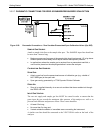
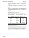
INPUT GAS VENTING
The zero air supply and sample gas line MUST be vented in order to ensure that the
gases input do not exceed the maximum inlet pressure of the analyzer as well as to
prevent back diffusion and pressure effects. These vents should be:
06864B DCN6314