


Teledyne API – Model T300/T300M CO Analyzer Setup Menu
99
Only active if the Optional
CO
2
or O
2
Sensor is
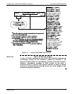
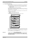
A
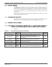
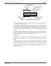
NALOG OUT
A1 A2 A3 A4
+ - + - + - + -
CO concentration
outputs
HIGH range when DUAL
mode is selected
Test Channel
LOW range when DUAL
mode is selected
Figure 5-1: Analog Output Connector Pin Out
The outputs can be configured either at the factory or by the user for full scale outputs of
0.1 VDC, 1VDC, 5VDC or 10VDC.
Additionally, A1, A2 and A3 may be equipped with optional 0-20 mADC current loop
drivers and configured for any current output within that range (e.g. 0-20, 2-20, 4-20,
etc.). The user may also adjust the signal level and scaling of the actual output voltage
or current to match the input requirements of the recorder or datalogger (See Section
5.9.3.9).
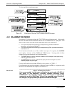
In its basic configuration,
the A1 and A2 channels output a signal that is proportional to
the CO
concentration of the sample gas. Several modes are available which allow them
to operate independently or be slaved together (See Section 5.4.3).
EXAMPLE:
A1 OUTPUT: Output Signal = 0-5 VDC representin
g 0-1000 ppm concentration values
A2 OUTPUT: Output Signal = 0 – 10 VDC representing 0-500 ppm concentration
values.
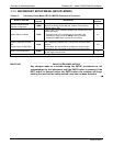
Output A3 is only active if the CO
2
or O
2
sensor option is installed. In this case a signal
representing the currently measured CO
2
or O
2
concentration is output on this channel.
The output, labeled A4 is special. It can be set by the user (See Section 5.9.8.1) to
output several of the test functions acce
ssible through the <TST TST> buttons of the
units sample display.
06864B DCN6314