


Teledyne API – Model T300/T300M CO Analyzer Theory of Operation
319
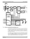
13.4.5.3. THERMISTOR INTERFACE
This circuit provides excitation, termination and signal selection for several negative-
coefficient, thermistor temperature sensors located inside the analyzer. They are as
follows:
S
AMPLE TEMPERATURE SENSOR
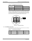
The source of this signal is a thermistor located inside the sample chamber of the Optical
Bench. It measures the temperature of the sample gas in the chamber. This data is used
to during the calculation of the CO concentration value.
B
ENCH TEMPERATURE SENSOR
This thermistor is attached to the sample chamber housing. It reports the current
temperature of the chamber housing to the CPU as part of the bench heater control loop.
W
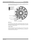
HEEL TEMPERATURE SENSOR
This thermistor is attached to the heatsink on the GFC Wheel motor assembly. It reports
the current temperature of the wheel/motor assembly to the CPU as part of the Wheel
Heater control loop.
B
OX TEMPERATURE SENSOR
A thermistor is attached to the motherboard. It measures the analyzer’s internal
temperature. This information is stored by the CPU and can be viewed by the user for
troubleshooting purposes via the front panel display (see Section 12.1.2).
13.4.5.4. ANALOG OUTPUTS
The analy
zer
comes equipped with four analog outputs: A1, A2, A3 and A4. The type
of data and electronic performance of these outputs are configurable by the user (see
Section 5.4).
O
UTPUT LOOP-BACK
All four analog outputs are connected back to the A/D converter through a loop-back
circuit. This permits the voltage outputs to be calibrated by the CPU without need for
any additional tools or fixtures.
13.4.5.5. INTERNAL DIGITAL I/O
This channel is used to
co
mmunicate digital status and control signals about the
operation of key components of the Optical Bench. The CPU sends signals to the
sync/demod board that initiate the ELECTRICAL TEST and DARK CALIBRATION
procedures.
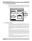
13.4.5.6. EXTERNAL DIGITAL I/O
This External Digital I/O perform
s two functions: status outp
uts and control inputs.
S
TATUS OUTPUTS
Logic-Level voltages are output through an optically isolated 8-pin connector located on
the rear panel of the analyzer. These outputs convey good/bad and on/off information
06864B DCN6314