


Teledyne API – Model T300/T300M CO Analyzer Troubleshooting and Service
259
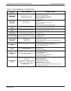
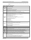
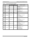
The following table contains some of the more common causes for these values to be out
of range.
Table 12-2: Test Functions - Indicated Failures
TEST
FUNCTIONS
(As Displayed)
INDICATED FAILURE(S)
TIME
Time of day clock is too fast or slow.
To adjust, see Section 5.6.
Battery in clock chip on CPU board may be dead.
RANGE
Incorrectly configured measurement range(s) could cause response problems with a Data logger or chart
recorder attached to one of the analog output.
If the Range selected is too small, the recording device will over range.
If the Range is too big, the device will show minimal or no apparent change in readings.
STABIL
Indicates noise level of instrument or CO concentration of sample gas (see Section 12.4.2 for causes).
CO MEAS
&
CO REF
If the value displayed is too high the IR Source has become brighter. Adjust the variable gain potentiometer on
the sync/demod board (see Section 12.5.7.1).
If the value disp
layed is too low or constantly changing and the CO REF is OK:
Failed multiplexer on the motherboard
Failed sync/demod board
Loose connector or wiring on sync/demod board
If the value displayed is too low or constantly changing and the CO REF is bad:
GFC Wheel stopped or rotation is too slow
Failed sync/demod board IR source
Failed IR source
Failed relay board
Failed I
2
C bus
Failed IR photo-detector
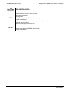
MR Ratio
When the analyzer is sampling zero air and the ratio is too low:
The reference cell of the GFC Wheel is contaminated or leaking.
The alignment between the GFC Wheel and the segment sensor, the M/R sensor or both is incorrect.
Failed sync/demod board
When the analyzer is sampling zero air and the ratio is too high:
Zero air is contaminated
Failed IR photo-detector
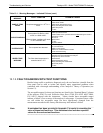
PRES
See Table 12-1 for SAMPLE PRES WARN.
SAMPLE FL
Check for gas flow problems (see Section 12.2).
SAMP TEMP
SAMPLE TEMP should be close to BENCH TEMP. Temperatures outside of the specified range or oscillating
temperatures are cause for concern.
BENCH
TEMP
Bench temp control improves instrument noise, stability and drift. Temperatures outside of the specified range
or oscillating temperatures are cause for concern. Table 12-1 for BENCH TEMP WARNING.
WHEEL
TEMP
Wheel temp control improves instrument noise, stability and drift. Outside of set point or oscillating
temperatures are causes for concern. See Table 12-1 for WHEEL TEMP WARNING.
BOX TEMP
If the box temperature is out of range, check fan in the power supply module. Areas to the side and rear of
instrument should allow adequate ventilation. See Table 12-1 for BOX TEMP WARNING.
PHT DRIVE
If this drive voltage is out of range it may indicate one of several problems:
A poor mechanical connection between the photodetector, its associated mounting hardware and the
absorption cell housing;
An electronic failure of the IR Photo-Detector’s built-in cooling circuitry, or;
A temperature problem inside the analyzer chassis. In this case other temperature warnings would also be
active such as BENCH TEMP WARNING or BOX TEMP WARNING.
06864B DCN6314