


Getting Started Teledyne API – Model T300/T300M CO Analyzer
48
A
NALOG OUT
A1
A
2 A3 A4
+ - + - + - + -
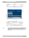
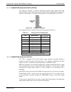
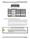
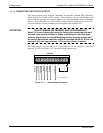
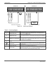
Figure 3-9: Analog Output Connector
Table 3-5: Analog Output Pin-Outs
PIN ANALOG OUTPUT VOLTAGE SIGNAL CURRENT SIGNAL
1 V Out I Out +
2
A1
Ground I Out -
3 V Out I Out +
4
A2
Ground I Out -
5 V Out I Out +
6
A3
(Only used if CO
2
or
O
2
Sensor is
installed)
Ground I Out -
7 V Out I Out +
8
A4
Ground I Out -
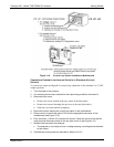
3.3.1.4. CURRENT LOOP ANALOG OUTPUTS (OPTION 41) SETUP
If your analyzer had this option installed at the factory, there are no further connections
to be made. Otherwise, it can be installed as a retrofit for each of the analog outputs of
the analyzer . This option converts the DC voltage analog output to a current signal with
0-20 mA output current. The outputs can be scaled to any set of limits within that 0-20
mA range. However, most current loop applications call for either 2-20 mA or 4-20 mA
range.
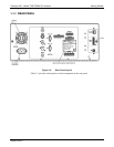
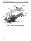
Figure 3-10 provides installation instructions and illustrates a s
a
mple combination of
one current output and two voltage outputs configuration. Following Figure 3-10 are
instructions for converting current loop
analog outputs to standard 0-to-5 VDC outputs.
Information on calibrating or adjusting these outputs can be found in Section 5.9.3.7
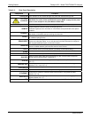
CAUTION – AVOID INVALIDATING WARRANTY
Servicing or handling of circuit components requires electrostatic
discharge protection, i.e. ESD grounding straps, mats and containers.
Failure to use ESD protection when working with electronic assemblies will
void the instrument warranty. Refer to Section 14 for more information on
preventing ESD damage.
06864B DCN6314