


Teledyne API – Model T300/T300M CO Analyzer Troubleshooting and Service
265
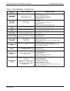
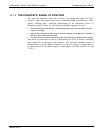
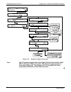
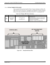
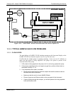
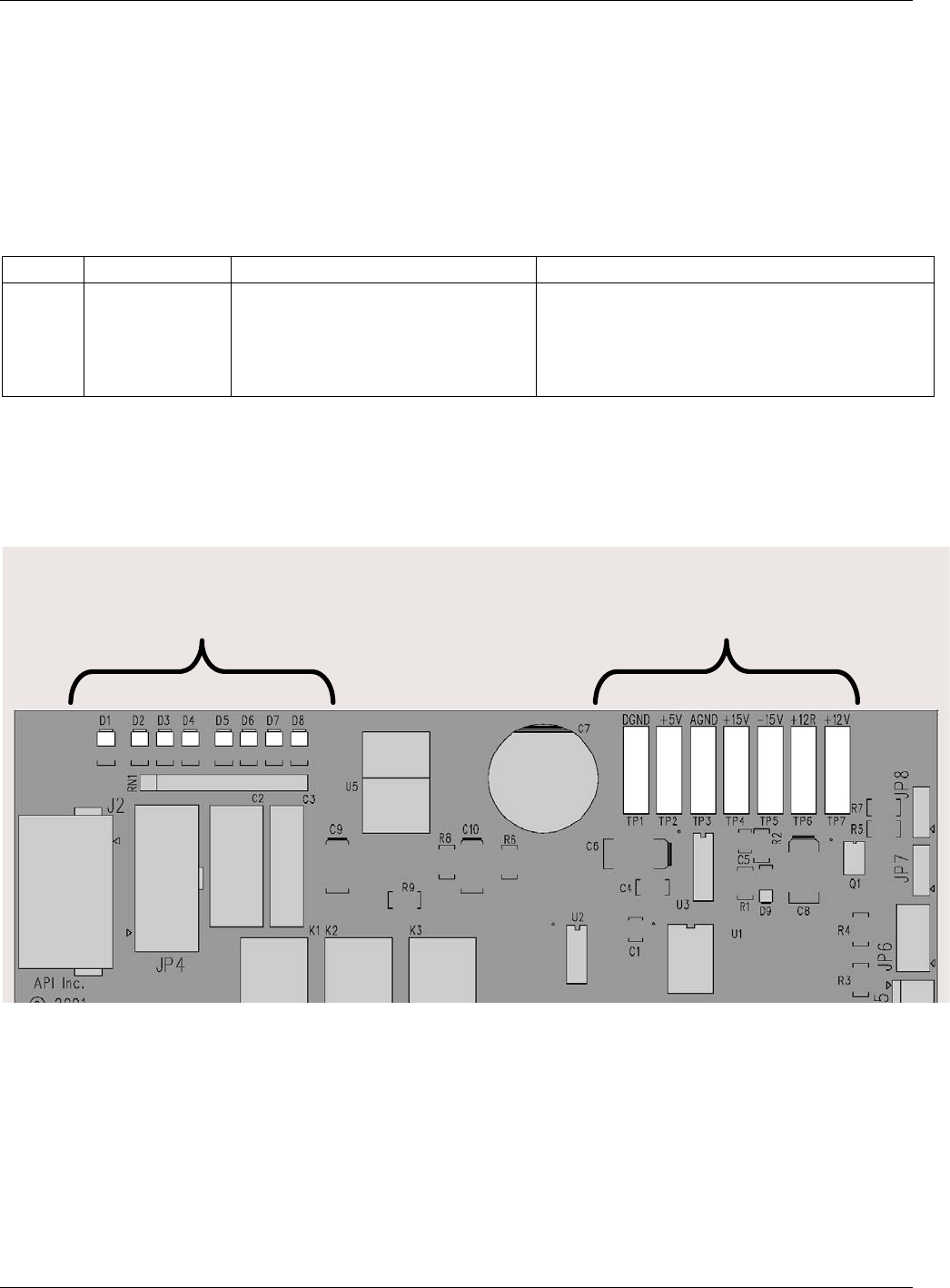
12.1.4.3. RELAY BOARD STATUS LEDS
There are eight LEDs located on the Relay Board. The most important of which is D1,
which indicates the health of the I
2
C bus. If D1 is blinking the other faults following
LEDs can be used in conjunction with DIAG menu signal I/O to identify hardware
failures of the relays and switches on the relay (see Section 12.1.3 and Appendix D).
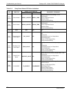
Table 12-4: I
2
C Status LED Failure Indications
LED FUNCTION FAULT STATUS INDICATED FAILURE(S)
D1
(Red)
I
2
C bus Health
(Watch Dog
Circuit)
Continuously ON
or
Continuously OFF
Failed/Halted CPU
Faulty Motherboard, Touchscreen or Relay Board
Faulty Connectors/Wiring between Motherboard,
Touchscreen or Relay Board
Failed/Faulty +5 VDC Power Supply (PS1)
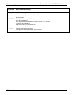
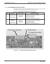
STATUS LED’s
DC VOLTAGE TEST
POINTS
RELAY PCA
PN 04135
Figure 12-5: Relay Board Status LEDs
06864B DCN6314