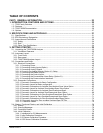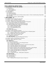
Table of Contents Teledyne API – Model T300/T300M CO Analyzer
xii
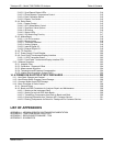
PART II OPERATING INSTRUCTIONS.................................................................................. 87
4. OVERVIEW OF OPERATING MODES ............................................................................... 89
4.1. Sample Mode...............................................................................................................................................90
4.1.1. Test Functions .......................................................................................................................................90
4.1.2. Warning Messages ................................................................................................................................93
4.2. Calibration Mode..........................................................................................................................................94
4.3. Setup MODE................................................................................................................................................95
4.3.1. Password Security .................................................................................................................................95
4.3.2. Primary Setup Menu ..............................................................................................................................95
4.3.3. The areas accessible under the Setup mode are shown in Table 4-4 and Secondary Setup Menu
(SETUP>MORE)..............................................................................................................................................95
4.3.4. Secondary Setup Menu (SETUP>MORE).............................................................................................96
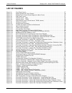
5. SETUP MENU 97
5.1. SETUP CFG: Configuration Information .................................................................................................97
5.2. SETUP ACAL: Automatic Calibration......................................................................................................98
5.3. SETUP DAS: Internal Data Acquisition System.......................................................................................98
5.4. SETUP RNGE: Analog Output Reporting Range Configuration .............................................................98
5.4.1. Analog Output Ranges for CO Concentration .......................................................................................98
5.4.2. Physical Range vs Analog Output Reporting Ranges ........................................................................ 100
5.4.3. Reporting Range Modes: Single, Dual, Auto Ranges ........................................................................ 100
5.4.3.1. SINGLE Range Mode (SNGL) .................................................................................................... 102
5.4.3.2. DUAL Range Mode (DUAL) ........................................................................................................ 103
5.4.3.3. AUTO Range Mode (AUTO) ....................................................................................................... 105
5.4.4. Range Units ........................................................................................................................................ 107
5.4.5. Dilution Ratio (Option)......................................................................................................................... 108
5.5. SETUP PASS: Password Protection.................................................................................................... 109
5.6. SETUP CLK: Setting the Internal Time-of-Day Clock and Adjusting Speed........................................ 111
5.6.1.1. Setting the Internal Clock’s Time and Day .................................................................................. 111
5.6.1.2. Adjusting the Internal Clock’s Speed........................................................................................... 111
5.7. SETUP Comm: Communications Ports ................................................................................................ 113
5.7.1. ID (Machine Identification) .................................................................................................................. 113
5.7.2. INET (Ethernet)................................................................................................................................... 113
5.7.3. COM1 and COM2 (Mode, Baud Rate and Test Port)......................................................................... 113
5.8. SETUP VARS: Variables Setup and Definition ..................................................................................... 114
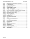
5.9. SETUP Diag: Diagnostics Functions..................................................................................................... 116
5.9.1. Signal I/O ............................................................................................................................................ 118
5.9.2. Analog Output ..................................................................................................................................... 119
5.9.3. Analog I/O Configuration..................................................................................................................... 120
5.9.3.1. Analog Output Voltage / Current Range Selection...................................................................... 122
5.9.3.2. Analog Output Calibration ........................................................................................................... 124
5.9.3.3. Enabling or Disabling the AutoCal for an Individual Analog Output............................................ 124
5.9.3.4. Automatic Calibration of the Analog Outputs .............................................................................. 126
5.9.3.5. Individual Calibration of the Analog Outputs ............................................................................... 127
5.9.3.6. Manual Calibration of the Analog Outputs Configured for Voltage Ranges................................ 128
5.9.3.7. Manual Adjustment of Current Loop Output Span and Offset .................................................... 130
5.9.3.8. Turning an Analog Output Over-Range Feature ON/OFF .......................................................... 133
5.9.3.9. Adding a Recorder Offset to an Analog Output........................................................................... 134
5.9.3.10. AIN Calibration .......................................................................................................................... 135
5.9.3.11. Analog Inputs (XIN1…XIN8) Option Configuration ................................................................... 136
5.9.4. Electrical Test ..................................................................................................................................... 137
5.9.5. Dark Calibration .................................................................................................................................. 137
5.9.6. Pressure Calibration ........................................................................................................................... 137
5.9.7. Flow Calibration .................................................................................................................................. 138
5.9.8. Test Chan Output................................................................................................................................ 138
5.9.8.1. Selecting a Test Channel Function for Output A4....................................................................... 138
06864B DCN6314


