


Teledyne API – Model T300/T300M CO Analyzer Getting Started
59
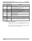
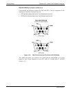
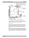
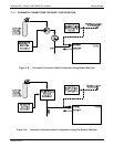
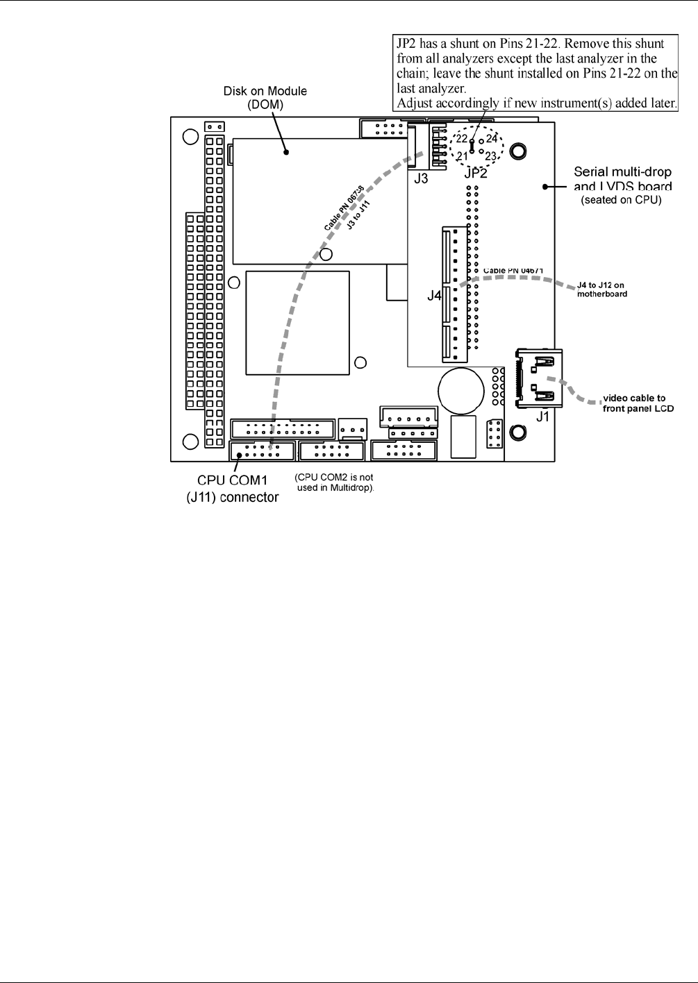
Figure 3-16: Jumper and Cables for Multidrop Mode
Note: If you are adding an instrument to the end of a previously configured chain,
remove the shunt between Pins 21 22 of JP2 on the Multidrop/LVDS PCA in the
instrument that was previously the last instrument in the chain.
4. Close the instrument.
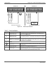
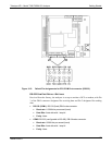
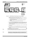
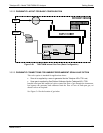
5. Referring to Figure 3-17 use straight-through DB9 male DB9 female ca
bles to
interconnect the host RS232 port to the first analyzer’s RS232 port; then from the
first analyzer’s COM2 port to the second analyzer’s RS232 port; from the second
analyzer’s COM2 port to the third analyzer’s RS232 port, etc., connecting in this
fashion up to eight analyzers, subject to the distance limitations of the RS-232
standard.
6. On the rear panel of each analyzer, adjust the DCE DTE switch so that the green
and the red LEDs (RX and TX) of the COM1 connector (labeled RS232) are both lit.
(Ensure you are using the correct RS-232 cables internally wired specifically for RS-
232 communication; see Table 1-1: Analyzer Options, “Communication Cables” and
Section 3.3.1.8: Connecting the Communications
Inerfac
es, “RS-232 Connection”).
06864B DCN6314