


Teledyne API – Model T300/T300M CO Analyzer Calibration Procedures
205
9.3. MANUAL CALIBRATION WITH ZERO/SPAN VALVES
There are a variety of valve options available on the T300/T300M for handling
calibration gases (see Table 1-1 for descriptions of each).
Generally perform
ing calibration checks and zero/span point calibrations on analyzers
with these options installed is similar to the methods discussed in the previous sections
of this section. The primary differences are:
On instruments with Z/S valve options, zero air and span gas is supplied to the
analyzer through other gas inlets besides the sample gas inlet.
The zero and span calibration operations are initiated directly and independently
with dedicated buttons (CALZ & CALS).
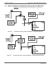
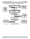
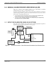
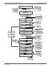
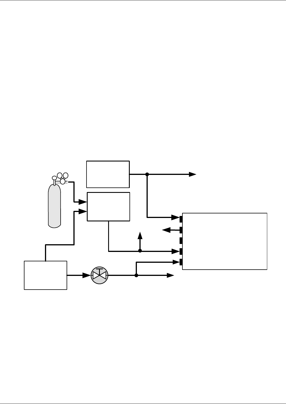
9.3.1. SETUP FOR CALIBRATION USING VALVE OPTIONS
Each of the various calibration valve options requires a different pneumatic setup that is
dependent on the exact nature and number of valves present.
Source of
SAMPLE GAS
Removed during
calibration
MODEL 701
Zero Gas
Generator
Calibrated
CO Gas
at span gas
concentration
VENT here if input
is pressurized
PRESSURE SPAN
ZERO AIR
SAMPLE
EXHAUST
VENT SPAN
Model 700 gas
Dilution
Calibrator
VENT
VENT
Instrument
Chassis
Figure 9-3: Pneumatic Connections – Option 50A: Ambient Zero/Ambient Span Calibration Valves
06864B DCN6314