


Teledyne API – Model T300/T300M CO Analyzer Getting Started
53
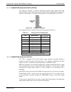
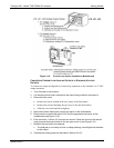
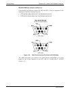
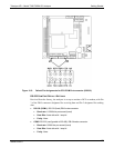
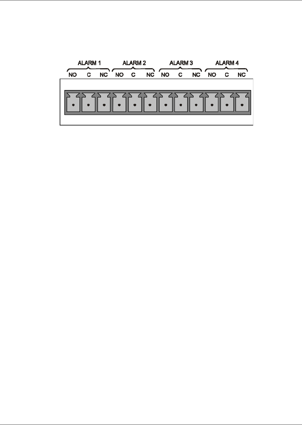
3.3.1.7. CONNECTING THE CONCENTRATION ALARM RELAY (OPTION 61)
The concentration alarm option is comprised of four (4) “dry contact” relays on the rear
panel of the instrument. This relay option is different from and in addition to the
“Contact Closures” that come standard on all Teledyne API instruments. Each relay has
3 pins: Normally Open (NO), Common (C), and Normally Closed (NC).
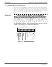
Figure 3-13: Concentration Alarm Relay
Alarm 1 “System OK 2”
Alarm 2 “Conc 1”
Alarm 3 “Conc 2”
Alarm 4 “Range Bit”
“ALARM 1” RELAY
Alarm 1 which is “System OK 2” (system OK 1, is the status bit) is in the energized
state when the instrument is “OK” & there are no warnings. If there is a warning active
or if the instrument is put into the “DIAG” mode, Alarm 1 will change states. This
alarm has “reverse logic” meaning that if you put a meter across the Common &
Normally Closed pins on the connector you will find that it is OPEN when the
instrument is OK. This is so that if the instrument should turn off or lose power, it will
change states and you can record this with a data logger or other recording device.
“A
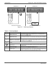
LARM 2” RELAY & “ALARM 3” RELAY
Alarm 2 relay is associated with the “Concentration Alarm 1” set point in the software;
Alarm 3 Relay is associated with the “Concentration Alarm 2” set point in the software.
Alarm 2 Relay CO Alarm 1 = xxx PPM
Alarm 3 Relay CO
2
Alarm 2 = xxx PPM
Alarm 2 Relay CO Alarm 1 = xxx PPM
Alarm 3 Relay CO
2
Alarm 2 = xxx PPM
The Alarm 2 Relay will be turned on any time the concentration set-point is exceeded &
will return to its normal state when the concentration value goes back below the
concentration set-point.
Even though the relay on the rear panel is a NON-Latching alarm & resets when the
concentration goes back below the alarm set point, the warning on the front panel of the
06864B DCN6314