1 2 3 4 5 6
A
B
C
D
6
54321
D
C
B
A
APPROVALS
DRAWN
CHECKED
APPROVED
DATE
SIZE DRAWING NO. REVISION
SHEET
The information herein is the
property of API and is
submitted in strictest con-
Unauthorized use by anyone
fidence for reference only.
for any other purposes is
prohibited. This document or
any information contained
in it may not be duplicated
without proper authorization.
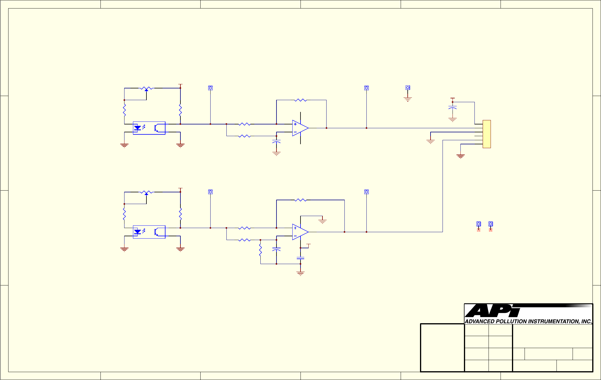
Schematics for PWB 05031
A
1 1
8-Jun-2004
LAST MOD.
B
of
RJ
5/17/04
05033
1
2
3
4
5
6
J1
R1
180
R10
2K
R2
2K
C2
1.0uF
+5V
TP4
R11
180
R4
220K
R8
100K
R5
100K
R3
10K
+5V
+5V
A
1
K
2
C
3
E
4
O2
OPB804
A
1
K
2
C
3
E
4
O1
OPB804
R6
10K
C1
1.0uF
and PCA 05032
OPTO-INTERRUPTER
TP2
TP1
C3
0.1uF
+5V
R9
162K
R7
100K
30Hz
360Hz
5
6
7
8 4
B
U1B
SN10502D
2
3
1
8 4
A
U1A
SN10502D
C4
1.0uF
MT2MT1
Mounting Holes
TP3
TP5
1
2
3
VR1 2K
1
2
3
VR2 2K
30HzRaw
30Hz
360HzRaw
360Hz
+30
+360
-30
-360
06864B DCN6314
D-13


