


Getting Started Teledyne API – Model T300/T300M CO Analyzer
54
instrument will remain latched until it is cleared. You can clear the warning on the front
panel by either pushing the CLR button on the front panel or through the serial port.
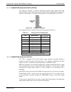
In instruments that sample more than one gas type, there could be more than one gas
type triggering the Concentration 1 Alarm (“Alarm 2” Relay). For example, the T300M
instrument can monitor both CO & CO
2
gas. The software is flexible enough to allow
you to configure the alarms so that you can have 2 alarm levels for each gas.
CO Alarm 1 = 20 PPM
CO Alarm 2 = 100 PPM
CO
2
Alarm 1 = 20 PPM
CO
2
Alarm 2 = 100 PPM
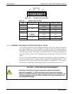
In this example, CO Alarm 1 & CO
2
Alarm 1 will both be associated with the “Alarm 2”
relay on the rear panel. This allows you do have multiple alarm levels for individual
gasses.
A more likely configuration for this would be to put one gas on the “Alarm 1” relay &
the other gas on the “Alarm 2” relay.
CO Alarm 1 = 20 PPM
CO Alarm 2 = Disabled
CO
2
Alarm 1 = Disabled
CO
2
Alarm 2 = 100 PPM
“A
LARM 4” RELAY
This relay is connected to the “range bit”. If the instrument is configured for “Auto
Range” and the instrument goes up into the high range, it will turn this relay on.
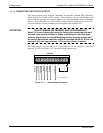
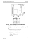
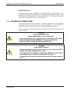
3.3.1.8. CONNECTING THE COMMUNICATION INTERFACES
The T-Series
analy
zers are equipped with connectors for remote communications
interfaces: Ethernet, USB, RS-232, optional RS-232 Multidrop, and optional RS-485.
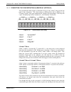
In addition to using the appropriate cables, each type of communication method must be
configured using the SETUP>COMM menu, Section 6. Although Ethernet is DHCP-
enabled by
default, it can also be configured manually (Section 6.5.1) to set up a static
IP address,
which is the recommended setting when operating the instrument via
Ethernet.
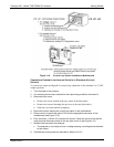
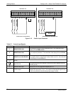
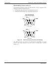
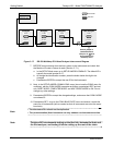
E
THERNET CONNECTION
For network or Internet communication with the analyzer, connect an Ethernet cable
from the analyzer’s rear panel Ethernet interface connector to an Ethernet access port.
Please see Section 6.5 for description and setup instructions.
For ma
nual configuration, see Section 6.5.1.
For automa
tic configuration (default), see Section 6.5.2.
06864B DCN6314