Table of Contents Teledyne API – Model T300/T300M CO Analyzer
xx
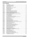
LIST OF TABLES
Table 1-1: Analyzer Options..........................................................................................................................27
Table 2-1: T300/T300M Basic Unit Specifications........................................................................................31
Table 2-2: O
2
Sensor Option Specifications..................................................................................................32
Table 2-3: CO
2
Sensor Option Specifications...............................................................................................33
Table 3-1: Ventilation Clearance...................................................................................................................36
Table 3-2: Display Screen and Touch Control Description...........................................................................39
Table 3-3: Rear Panel Description................................................................................................................42
Table 3-4: Analog Input Pin Assignments.....................................................................................................47
Table 3-5: Analog Output Pin-Outs...............................................................................................................48
Table 3-6: Status Output Signals ..................................................................................................................51
Table 3-7: Control Input Signals....................................................................................................................52
Table 3-8: Zero/Span Valve Operating States for Option 50A......................................................................67
Table 3-9: Zero/Span Valve Operating States for Option 50B......................................................................69
Table 3-10: Zero/Span Valve Operating States for Option 51E......................................................................71
Table 3-11: Zero/Span Valve Operating States for Option 50H .....................................................................74
Table 3-12: NIST-SRM's Available for Traceability of CO Calibration Gases..................................................75
Table 3-13: Possible Warning Messages at Start-Up .....................................................................................77
Table 3-14: Possible Startup Warning Messages – T300 Analyzers with Options.........................................78
Table 4-1: Analyzer Operating Modes ..........................................................................................................90
Table 4-2: Test Functions Defined................................................................................................................92
Table 4-3: List of Warning Messages............................................................................................................93
Table 4-4: Primary Setup Mode Features and Functions .............................................................................95
Table 4-5: Secondary Setup Mode (SETUP>MORE) Features and Functions............................................96
Table 5-1: T300 Family Physical Range by Model .................................................................................... 100
Table 5-2: Password Levels....................................................................................................................... 109
Table 5-3: Variable Names (VARS) ........................................................................................................... 114
Table 5-4: Diagnostic Mode (DIAG) Functions .......................................................................................... 116
Table 5-5: DIAG - Analog I/O Functions .................................................................................................... 120
Table 5-6: Analog Output Voltage Ranges ................................................................................................ 122
Table 5-7: Voltage Tolerances for the TEST CHANNEL Calibration......................................................... 128
Table 5-8: Current Loop Output Check...................................................................................................... 132
Table 5-9: Test Channels Functions available on the T300/T300M’s Analog Output ............................... 138
Table 5-10: CO Concentration Alarm Default Settings ................................................................................ 140
Table 6-1: COMM Port Communication Modes ......................................................................................... 144
Table 6-2: Ethernet Status Indicators......................................................................................................... 148
Table 6-3: LAN/Internet Default Configuration Properties ......................................................................... 149
Table 6-4: RS-232 Communication Parameters for Hessen Protocol ....................................................... 157
Table 6-5: Teledyne API’s Hessen Protocol Response Modes ................................................................. 161
Table 6-6: Default Hessen Status Flag Assignments ................................................................................ 165
Table 7-1: Front Panel LED Status Indicators for DAS.............................................................................. 167
Table 7-2: DAS Data Channel Properties .................................................................................................. 169
Table 7-3: DAS Data Parameter Functions ............................................................................................... 176
Table 8-1: Interactive Mode Software Commands..................................................................................... 190
Table 8-2: Teledyne API’s Serial I/O Command Types ............................................................................. 191
Table 9-1: NIST-SRMs Available for Traceability of CO Calibration Gases ............................................... 198
Table 9-2: AUTOCAL Modes ..................................................................................................................... 212
Table 9-3: AutoCal Attribute Setup Parameters......................................................................................... 213
Table 9-4: Example AutoCal Sequence..................................................................................................... 214
Table 9-5: Calibration Data Quality Evaluation.......................................................................................... 218
Table 10-1: Matrix for Calibration Equipment & Supplies ............................................................................ 233
Table 10-2: Activity Matrix for Quality Assurance Checks ........................................................................... 234
Table 10-3: Definition of Level 1 and Level 2 Zero and Span Checks......................................................... 235
Table 11-1: T300/T300M Maintenance Schedule........................................................................................ 247
Table 11-2: T300/T300M Test Function Record .......................................................................................... 248
06864B DCN6314


