


Remote Operation Teledyne API – Model T300/T300M CO Analyzer
192
8.2.1.4. STATUS REPORTING
Reporting of status messages as an audit trail is one of the three principal uses for the
RS-232 interface (the other two being the command line interface for controlling the
instrument and the download of data in electronic format). You can effectively disable
the reporting feature by setting the interface to quiet mode (see Section 6.2.1, Table 6-1).
Status reports include warning mess
ages, calibration and diagnostic status messages.
Refer to Appendix A-3 for a list of the possible messages, and this for information on
controlling the instrument through the RS-232 interface.
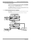
8.2.1.5. GENERAL MESSAGE FORMAT
All
m
essages from the instrument (including those in response to a command line
request) are in the format:
X DDD:HH:MM [Id] MESSAGE<CRLF>
Where:
X is a command type designator, a single character indicating the
message type, as shown in the Table 8-2.
DDD:HH:MM
is the time stamp, the date and time when the message was issued. It
consists of the Day-of-year (DDD) as a number from 1 to 366, the hour
of the day (HH) as a number from 00 to 23, and the minute (MM) as a
number from 00 to 59.
[ID] is the analyzer ID, a number with 1 to 4 digits.
MESSAGE is the message content that may contain warning messages, test
measurements, variable values, etc.
<CRLF> is a carriage return / line feed pair, which terminates the message.
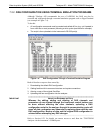
The uniform nature of the output messages makes it easy for a host computer to parse
them into an easy structure. Keep in mind that the front panel display does not give any
information on the time a message was issued, hence it is useful to log such messages
for trouble-shooting and reference purposes. Terminal emulation programs such as
HyperTerminal can capture these messages to text files for later review.
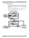
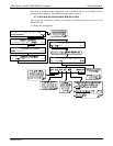
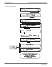
8.3. REMOTE ACCESS BY MODEM
The T300/T300M can be connected to a modem for remote access. This requires a cable
between the analyzer’s COMM port and the modem, typically a DB-9F to DB-25M
cable (available from Teledyne API with P/N WR0000024).
Once the cable has been connected, check to make sure:
The DTE-DCE is in the DCE position.
The T300/T300M COMM port is set for a baud rate that is compatible with the
modem,
The modem is designed to operate with an 8-bit word length with one stop bit.
The MODEM ENABLE communication mode is turned on (Mode 64, see Table 6-1).
06864B DCN6314