


Teledyne API – Model T300/T300M CO Analyzer Getting Started
51
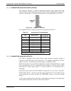
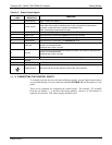
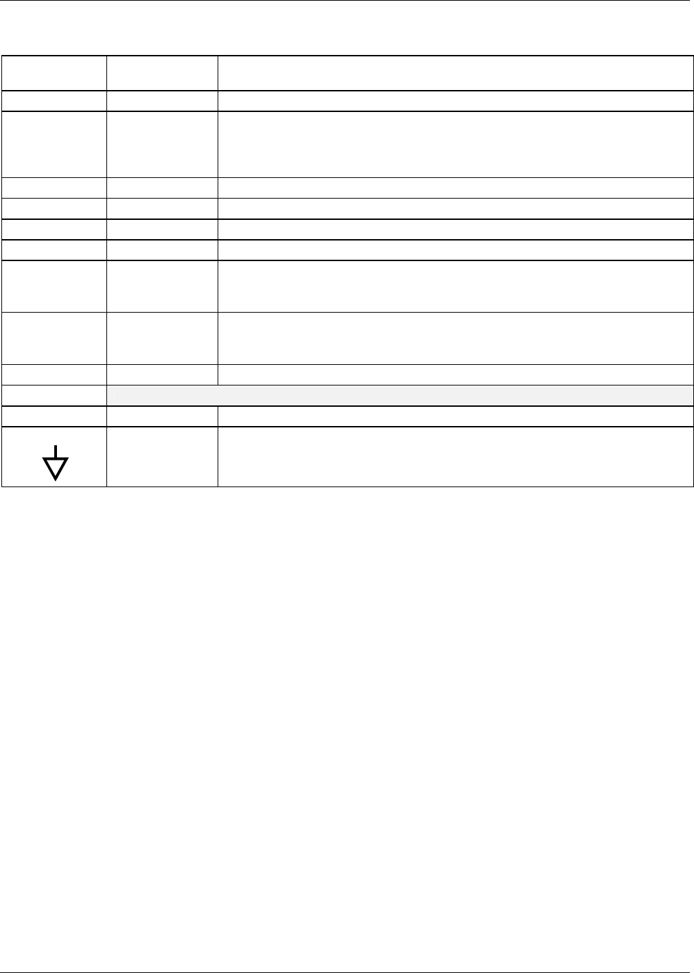
Table 3-6: Status Output Signals
REAR PANEL
LABEL
STATUS
DEFINITION
CONDITION
1 SYSTEM OK ON if no faults are present.
2 CONC VALID
OFF any time the HOLD OFF feature is active, such as during calibration or when
other faults exist possibly invalidating the current concentration measurement
(example: sample flow rate is outside of acceptable limits).
ON if concentration measurement is valid.
3 HIGH RANGE
ON if unit is in high range of either the DUAL or AUTO range modes.
4 ZERO CAL
ON whenever the instrument’s ZERO point is being calibrated.
5 SPAN CAL
ON whenever the instrument’s SPAN point is being calibrated.
6 DIAG MODE
ON whenever the instrument is in DIAGNOSTIC mode.
7 CO
2
CAL
If this analyzer is equipped with an optional CO
2
sensor, this Output is ON when that
sensor is in calibration mode.
Otherwise this output is unused.
8 O
2
CAL
If this analyzer is equipped with an optional O
2
sensor, this Output is ON when that
sensor is in calibration mode.
Otherwise this output is unused.
D EMITTER BUS The emitters of the transistors on pins 1-8 are bussed together.
SPARE
+ DC POWER + 5 VDC, 300 mA source maximum.
Digital Ground The ground level from the analyzer’s internal DC power supplies.
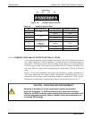
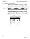
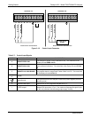
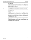
3.3.1.6. CONNECTING THE CONTROL INPUTS
To remotely activate the zero and span calibration modes, several digital control inputs
are provided through a 10-pin connector labeled CONTROL IN on the analyzer’s rear
panel.
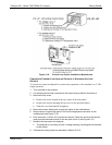
There are two methods for energizing the control inputs. The internal +5V available
from the pin labeled “+” is the most convenient method. However, if full isolation is
required, an external 5 VDC power supply should be used.
06864B DCN6314