


Theory of Operation Teledyne API – Model T300/T300M CO Analyzer
312
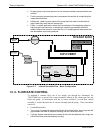
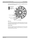
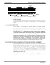
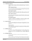
Reference
Pulses
Measurement
Pulses
IR Beam
Pulses
Segment Sensor
Pulses
MR Sensor
Pulses
Figure 13-12: Segment Sensor and M/R Sensor Output
SCHMIDT TRIGGERS
To ensure that the waveforms produced by the Segment Sensor and the M/R Sensor are
properly shaped and clean, these signals are passed through a set of Schmidt Triggers
circuits.
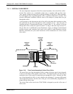
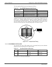
13.4.2.4. IR PHOTO-DETECTOR
The IR beam is converted into an electrical signal by a cooled
solid-state
photo-conduc
tive detector. The detector is composed of a narrow-band optical filter, a
piece of lead-salt crystal whose electrical resistance changes with temperature, and a
two-stage thermo-electric cooler.
When the analyzer is on, a constant electrical current is directed through the detector.
The IR beam is focused onto the detector surface, raising its temperature and lowering
its electrical resistance that results in a change in the voltage drop across the detector.
During those times that the IR beam is bright, the temperature of the detector is high; the
resistance of the detector is correspondingly low and its output voltage output is low.
During those times when the IR beam intensity is low or completely blocked by the
GFC Wheel mask, the temperature of the detector is lowered by the two-stage thermo-
electric cooler, increasing the detector’s resistance and raising the output voltage.
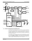
13.4.3. SYNCHRONOUS DEMODULATOR (SYNC/DEMOD) ASSEMBLY
While the photo-detector converts fluctuations of the IR beam into electronic signals, the
Sync/Demod Board amplifies these signals and converts them into usable information.
Initially the output by the photo-detector is a complex and continuously changing
waveform made up of Measure and Reference pulses. The sync/demod board
demodulates this waveform and outputs two analog DC voltage signals, corresponding
to the peak values of these pulses. CO MEAS and CO REF are converted into digital
signals by circuitry on the motherboard then used by the CPU to calculate the CO
concentration of the sample gas.
Additionally the synch/demod board contains circuitry that controls the photo-detector’s
thermoelectric cooler as well as circuitry for performing certain diagnostic tests on the
analyzer.
06864B DCN6314