


Troubleshooting and Service Teledyne API – Model T300/T300M CO Analyzer
276
3. If the relay has failed there should be no change in the voltage across pins 2 and 4
or 3 and 4. Note: K2 is in a socket for easy replacement.
4. If K2 checks out OK, the thermistor temperature sensor located on the optical bench
near the front of the instrument could be at fault.
Unplug the connector labeled “Bench”, and measure the resistance of the
thermistor.
At room temperature it should have approximately 30K Ohms resistance; near
the 48
o
C set point it should have ~12K ohms.
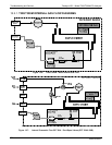
12.4.1.3. GFC WHEEL TEMPERATURE
Like the bench heater above there are three possible causes for the GFC Wheel
temperature to have failed.
1. The wheel heater has failed.
Check the resistance between pins 1 and 4 on the white five-pin connector just
below the sample temperature sensor on the bench (pin 1 is the pointed end).
It should be approximately 275 ohms.
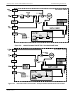
2. Assuming that the I
2
C bus is working and that there is no other failure with the relay
board; the solid-state relay (K1) on the relay board may have failed.
Using the WHEEL_HEATER parameter under the signal I/O function, as
described above, turn on and off K1 (D2 on the relay board should illuminate as
the heater is turned on).
Check the AC voltage present between pin 1 and 4.
WARNING - ELECTRICAL SHOCK HAZARD
Hazardous Voltages are present during this test.
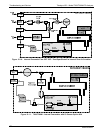
3. If the relay has failed there should be no change in the voltage across pins 1 and 4.
K1 is socketed for easy replacement.
4. If K1 checks out OK, the thermistor temperature sensor located at the front of the
filter wheel assembly may have failed.
5. Unplug the connector labeled “Wheel”, and measure the resistance of the
thermistor. The resistance near the 68°C set point is ~5.7k ohms.
06864B DCN6314