


Troubleshooting and Service Teledyne API – Model T300/T300M CO Analyzer
284
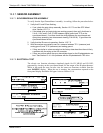
12.5.8. MOTHERBOARD
12.5.8.1. A/D FUNCTIONS
The simplest method to check the operation of the A-to-D converter on the motherboard
is to use the Signal I/O function under the DIAG menu to check the two A/D reference
voltages and input signals that can be easily measured with a voltmeter.
1. Use the Signal I/O function (see Section 12.1.3 and Appendix A) to view the value of
REF_4096_MV and REF_GND.
If both are within 3 mV of nominal (4096 and 0), and are stable, ±0.5 mV then
the basic A/D is functioning properly. If not then the motherboard is bad.
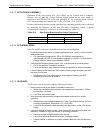
2. Choose a parameter in the Signal I/O function such as SAMPLE_PRESSURE,
SAMPLE_FLOW, CO_MEASURE or CO_REFERENCE.
Compare these voltages at their origin (see interconnect drawing, P/N 04215
and interconnect list, P/N 04216) with the voltage displayed through the signal
I/O function.
If the wiring is intact but there is a large difference between the measured and
displayed voltage (±10 mV) then the motherboard is bad.
See also Sections 5.9.1 and 12.1.3.
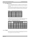
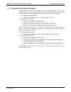
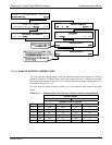
12.5.8.2. TEST CHANNEL / ANALOG OUTPUTS VOLTAGE
The ANALOG OUTP
UT submenu, located under the SETUP MORE DIAG
menu is used to verify that the T300/T300M Analyzer’s analog outputs are working
properly. The test generates a signal on functioning outputs simultaneously as shown in
the following table. (See also Section 5.9.2).
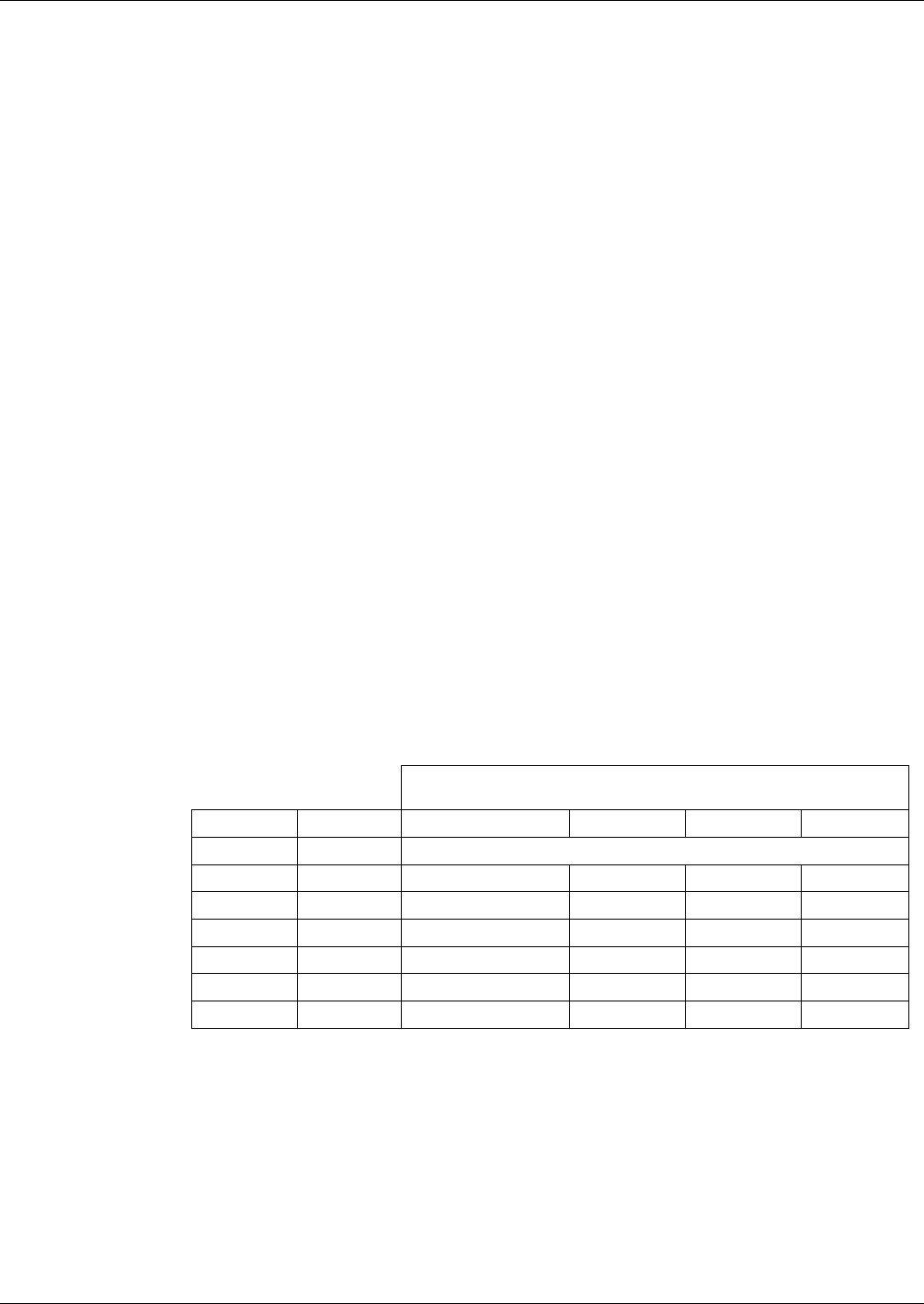
Table 12-10: Analog Output Test Function - Nominal Values Voltage Outputs
FULL SCALE OUTPUT OF VOLTAGE RANGE
(see Section 5.9.3.1)
100MV 1V 5V 10V
STEP % NOMINAL OUTPUT VOLTAGE
1 0 0 0 0 0
2 20 20 mV 0.2 1 2
3 40 40 mV 0.4 2 4
4 60 60 mV 0.6 3 6
5 80 80 mV 0.8 4 8
6 100 100 mV 1.0 5 10
For each of the steps the output should be within 1% of the nominal value listed in the
table below except for the 0% step, which should be within 0mV ±2 mV. Make sure
you take into account any offset that may have been programmed into channel (see
Section 5.9.3.9).
If one or m
ore of the steps fails to be within these ranges, it is likely that there has been
a failure of either or both of the DACs and their associated circuitry on the motherboard.
To perform the test connect a voltmeter to the output in question and perform an analog
output step test as follows:
06864B DCN6314