


Maintenance Schedule & Procedures Teledyne API – Model T300/T300M CO Analyzer
252
5. If the instrument has one of the zero and span valve options, the normally closed
ports on each valve should also be separately checked. Connect the leak checker
to the normally closed ports and check with soap bubble solution.
6. Once the leak has been located and repaired, the leak-down rate should be < 1 in-
Hg (0.4 psi) in 5 minutes after the pressure is shut off.
11.3.4. PERFORMING A SAMPLE FLOW CHECK
CAUTION
GENERAL SAFETY HAZARD
Always use a separate calibrated flow meter capable of measuring flows in the 0 – 1000
cm
3
/min range to measure the gas flow rate though the analyzer.
DO NOT use the built in flow measurement viewable from the Front Panel of the
instrument. This measurement is only for detecting major flow interruptions such as
clogged or plugged gas lines.
See Figure 3-4 for SAMPLE port location.
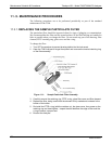
1. Attach the Flow Meter to the sample inlet port on the rear panel. Ensure that the
inlet to the Flow Meter is at atmospheric pressure.
2. Sample flow should be 800 cm
3
/min 10%.
3. Once an accurate measurement has been recorded by the method described
above, adjust the analyzer’s internal flow sensors (See Section 9.6.3).
Low flows indicate blockage somewhere in the pneumatic pathway, typically a plugged
sintered filter or critical flow orifice in one of the analyzer’s flow control assemblies.
High flows indicate leaks downstream of the Flow Control Assembly.
11.3.5. CLEANING THE OPTICAL BENCH
The T300/T300M sensor assembly and optical bench are complex and delicate.
Disassembly and cleaning is not recommended. Please check with the factory before
disassembling the optical bench.
11.3.6. CLEANING EXTERIOR SURFACES OF THE T300/T300M
If necessary, the exterior surfaces of the T300/T300M can be cleaned with a clean damp
cloth. Do NOT submerge any part of the instrument and do NOT use any cleaning
solution.
06864B DCN6314