


Reference Manual
300530EN, Rev BA
September 2012
3-15
Rosemount 2410
Section 3. Installation
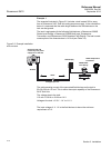
3.4.8 Typical
Installations
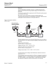
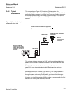
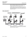
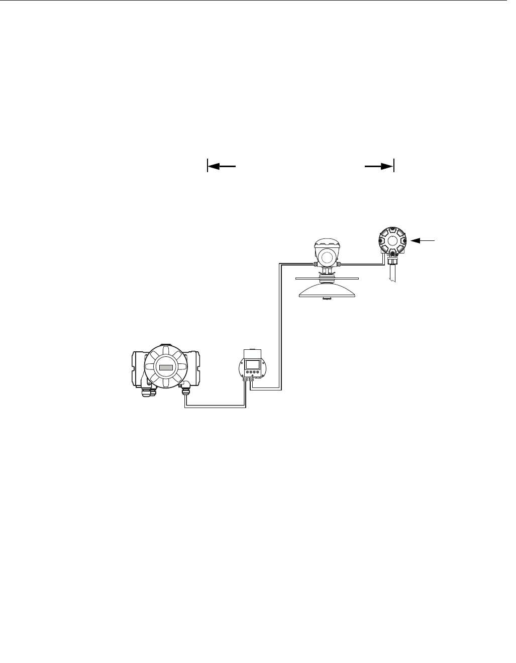
The example below (Figure 3-7) illustrates a Raptor system with
daisy-chained field devices on a single tank. Terminators are installed at both
ends of the fieldbus segment as required in a F
OUNDATION fieldbus system. In
this example the terminators are enabled in the Rosemount 2410 Tank Hub
and a Raptor field device (Rosemount 2240S) the end of the network
segment.
Figure 3-7. Example of a Raptor
system with single tank
The maximum distance between the 2410 Tank Hub and the field devices
depends on the number of devices connected to the Tankbus and the cable
type.
See “Cable Selection for the Tankbus” on page 3-6 and “Tankbus” on
page 3-8 for more information about cable selection and the Tankbus.
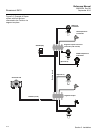
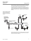
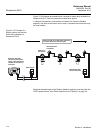
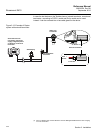
an example with a 2-in-1 version of the 5900S in a SIL safety installation. A
4-wire cable is used to connect the Primary and Secondary Tankbuses
through the same cable entry. The SIL alarm wire is connected through a
separate cable entry as illustrated in Figure 3-8.
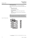
A junction box is used to provide sufficient number of connections for the field
devices to the Primary and Secondary Tankbus.
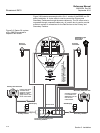
5900S Radar
Level Gauge
2240S Multi-input Temperature
Transmitter
Built-in
terminator
enabled on the
last device
2230 Display
2410 Tank Hub with
intrinsically safe power
supply, integrated power
conditioner, and built-in
terminator
Tankbus length up to 1000 meter depending
on number of devices and cable type
Tankbus