Reference Manual
300530EN, Rev BA
September 2012
Rosemount 2410
3-2
Section 3. Installation
3.2 INSTALLATION
CONSIDERATIONS
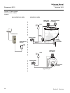
The Rosemount 2410 Tank Hub may be installed on various locations at the
plant. Mounting at the tank foot may be convenient when you would like to
have easy access to measuring data, diagnostics and other information on
the 2410 optional integral display.
The 2410 can also be mounted on the tank roof if this is the preferred location.
In case the 2410 is exposed to long periods of sunshine, a sunshade should
be used to prevent the 2410 Tank Hub from being heated to temperatures
above the maximum operating temperature.
Ensure that environmental conditions are within specified limits as listed in
Appendix A: Reference Data.
Ensure that the Rosemount 2410 is installed such that it is not exposed to
higher pressure and temperature than specified in Appendix A: Reference
Data.
The multi-tank version of the Rosemount 2410 Tank Hub is able to serve
several tanks. In that case the 2410 may be placed at a suitable location
further away from the tanks.
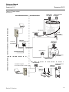
The 2410 is designed with two Tankbus terminals and several cable entries
which allows alternative cable routings to suit various requirements.
Do not install the Rosemount 2410 in non-intended applications, for example
environments where it may be exposed to extremely intense magnetic fields
or extreme weather conditions.
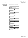
It’s a good idea to plan the installation in order ensure that all components in
the system are properly specified. The planning stage should include the
following tasks:
• make a plan of the site and specify suitable locations for the devices
• consider power budget
• specify cabling and connections (for example whether devices will be
“daisy-chained” or not)
• specify cable glands that will be needed for the various devices
• specify location of terminators on the Tankbus
• make a note of identification codes such as Unit ID/Device ID of each
device
• assign Modbus adresses for level gauges and other tank devices to be
used in the Tank Database of the 2410 and the Slave Database of the
2160 Field Communication Unit (see the Raptor System Configuration
manual, document no. 300510 for more information)
See “Electrical Installation” on page 3-5 for more information on cables and
glands.
IMPORTANT
Check the 2410 Tank Hub for any signs of damage prior to installation. Ensure
that the glass on the integral display is undamaged, and O-rings and gaskets
are in good condition.


