


Reference Manual
300530EN, Rev BA
September 2012
3-9
Rosemount 2410
Section 3. Installation
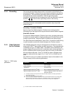
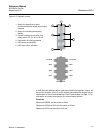
Since the field devices on the Tankbus must have at least a 9 V input voltage
at their terminals, you will have to take into account the voltage drop in the
fieldbus cables. Distances are normally quite short between the Rosemount
2410 Tank Hub and field devices on the tank. In many cases you can use
existing cables as long as the FISCO requirements are fulfilled (see “Cable
Selection for the Tankbus” on page 3-6). Typical characteristics for such a
cable is:
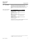
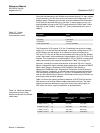
Table 3-3. Typical
characteristics of
instrumentation cable
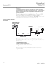
The Rosemount 2410 outputs 12.5 Vdc. Considering the minimum voltage
supply of 9 V on the field device terminals, a maximum voltage drop of 3.5 V
on the Tankbus can be allowed. At a maximum current consumption of
250 mA (12.5 Vdc) with all field devices located at the far end of the Tankbus,
a total “worst case” cable resistance of approximately 14 Ω (3.5 V/250 mA) is
allowed. This corresponds to a cable length of 333 m (1092 ft) in case typical
cable characteristics are assumed as specified in Table 3-3 on page 3-9.
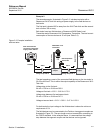
However, normally the current consumption is less than 250 mA. A typical
Raptor configuration would include a tank supplied with a Rosemount 5900S
Radar Level Gauge, a Rosemount 2230 Graphical Field Display, a
Rosemount 2240S Multi-input Temperature Transmitter, and a Rosemount
3051S Pressure Transmitter. In this case the current consumption would be
128 mA allowing a cable length of 677 m (2221 ft) between the 2410 Tank
Hub and the field devices on the tank. With fewer devices on the Tankbus, an
even longer cable would be allowed.
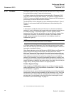
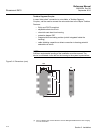
Table 3-4 shows the maximum distance between a 2410 Tank Hub and the
field devices on a tank for different cable cross-sectional areas. The table
shows the maximum distance to a tank at a total current consumption of
250 mA as well as for a typical installation as outlined above.
Table 3-4. Maximum distance
from power source to field
devices on the tank for different
cable areas
Parameter Value
Loop resistance 42 /km
Inductance 0.65 mH/km
Capacitance 115 nF/km
Cross-sectional area 0.75 mm
2
(18 AWG)
Cable characteristics Maximum distance to tank (m/ft)
Cross-sectional area Typical loop
resistance
/km)
Maximum Current
consumption
(250 mA)
Typical installation
(128 mA)
20 AWG (0.5 mm
2
) 66 212 (695) 414 (1358)
18 AWG (0.75 mm
2
) 42 333 (1092) 651 (2136)
17 AWG (1.0 mm
2
) 33 424 (1391) 829 (2720)
16 AWG (1.5 mm
2
) 26 538 (1765) 1052 (3451)