


Reference Manual
300530EN, Rev BA
September 2012
Rosemount 2410
3-10
Section 3. Installation
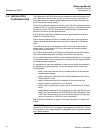
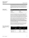
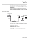
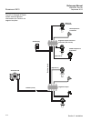
Example 1
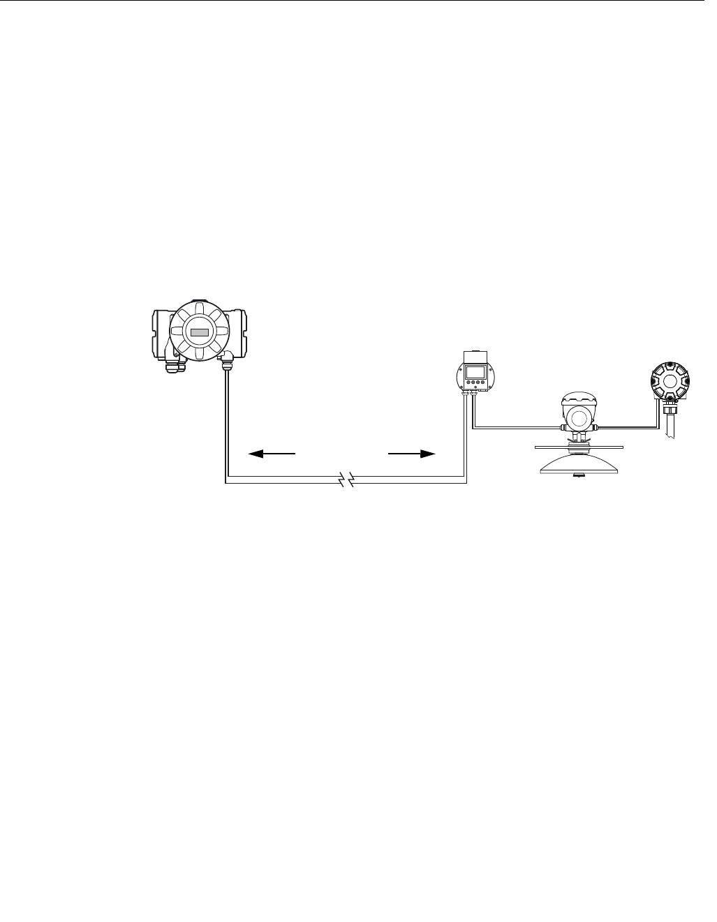
The example illustrated in Figure 3-2 includes a tank located 300 m away
from a Rosemount 2410 Tank Hub acting as power supply. In the calculations
below it is assumed that the cable length between the field devices on the
tank can be ignored.
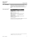
The tank is equipped with the following field devices: a Rosemount 5900S
Radar Level Gauge, a Rosemount 2240S Multi-input Temperature
Transmitter, and a Rosemount 2230 Graphical Field Display. The total current
consumption of the three devices is 110 mA (see Table 3-2).
Figure 3-2. Example installation
with one tank
The total operating current of the connected field devices on the tank is
50+30+30 mA=110 mA. This is within the output capability of the Rosemount
2410 Tank Hub.
The voltage drop to the tank:
110 mA x 0.30 km x 42 /km=1.4 V.
Voltage at the tank =12.5 V - 1.4 V=11.1 V.
The input voltage of 11.1 V to the field devices is above the minimum
requirement of 9 V.
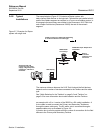
2410 Tank Hub with
intrinsically safe power
supply:12.5 V, 250 mA
5900S Radar
Level Gauge
2230 Display
300 m
Voltage drop=1.3 V
Tankbus
2240S Temperature
Transmitter