77
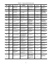
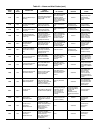
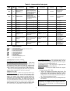
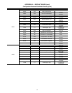
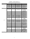
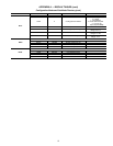
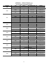
APPENDIX A — DISPLAY TABLES (cont)
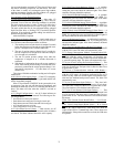
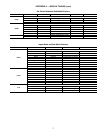
Set Points Mode and Sub-Mode Directory
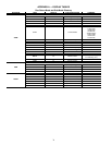
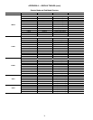
Inputs Mode and Sub-Mode Directory
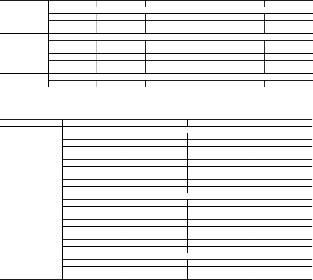
SUB-MODE ITEM DISPLAY ITEM DESCRIPTION RANGE COMMENT
COOL
COOLING SET POINTS
CSP.1 xxx.x °F Cooling Set Point 1 –20 to 70 Default: 44 F
CSP.2 xxx.x °F Cooling Set Point 2 –20 to 70 Default: 44 F
CSP.3 xxx.x °F ICE Set Point –20 to 32 Default: 32 F
HEAD
HEAD PRESSURE SET POINTS
H.DP xxx.x °F Head Set Point 85 to 120 Default: 95 F
F.ON xxx.x °F Fan On Set Point Default: 95 F
F.OFF xxx.x °F Fan Off Set Point Default: 72 F
B.OFF xx.x Base Fan Off Delta Temp 10 to 50 Default: 23 F
F.DLT xxx Fan Stage Delta 0 to 50 Default: 15 F
FRZ
BRINE FREEZE SET POINT
BR.FZ xx.x °F Brine Freeze Point –20 to 34 Default: 34 F
SUB-MODE ITEM DISPLAY ITEM DESCRIPTION COMMENT
GEN.I
GENERAL INPUTS
STST ON/OFF Start/Stop Switch
FLOW ON/OFF Cooler Flow Switch
PM.F.1 ON/OFF Cooler Pump 1 Interlock
PM.F.2 ON/OFF Cooler Pump 2 Interlock
HT.RQ ON/OFF Heat Request
DLS1 ON/OFF Demand Limit Switch 1
DLS2 ON/OFF Demand Limit Switch 2
ICED ON/OFF Ice Done
DUAL ON/OFF Dual Set Point Switch
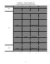
CRCT
CIRCUIT INPUTS
FKA1 ON/OFF Compressor A1 Feedback
FKA2 ON/OFF Compressor A2 Feedback
FKA3 ON/OFF Compressor A3 Feedback
FKA4 ON/OFF Compressor A4 Feedback
FKB1 ON/OFF Compressor B1 Feedback
FKB2 ON/OFF Compressor B2 Feedback
FKB3 ON/OFF Compressor B3 Feedback
FKB4 ON/OFF Compressor B4 Feedback
4-20
4-20 MA INPUTS
DMND xx.x 4-20 ma Demand Signal
RSET xx.x 4-20 ma Reset Signal
CSP xx.x 4-20 ma Cooling Set Point


