


73
rise to greater than the maximum SCT, the alert will occur and
the circuit's remaining compressor will shut down. The cause
of the alarm is usually an overcharged system, high outdoor
ambient temperature coupled with dirty outdoor coil, plugged
filter drier, or a faulty high-pressure switch.
T133 (Circuit A Low Suction Pressure)
T134 (Circuit B Low Suction Pressure) — Alert codes 133
and 134 are for circuits A and B respectively. These alerts are
generated if one of the two following conditions is satisfied:
the circuit suction pressure is below 34 psig (234.4 kPa) for 8
seconds, or the suction pressure is below 23 psig (158.6 kPa).
The cause of this alert may be low refrigerant charge, plugged
liquid line filter drier, or sticking EXV. Check head pressure
operation. If not equipped, consider adding low ambient tem-
perature head pressure control.
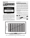
Add wind baffles if required.
A140 (Reverse Rotation Detected)
— A test is made once, on
power up, for suction pressure change on the first activated cir-
cuit. The unit control determines failure as follows:
1. The suction pressure of both circuits is sampled 5 seconds
before the compressor is brought on, right when the com-
pressor is brought on and 5 seconds afterwards.
2. The rate of suction pressure change from 5 seconds be-
fore the compressor is brought on to when the compres-
sor is brought on is calculated.
3. The rate of suction pressure change from when the
compressor is brought on to 5 seconds afterwards is
calculated.
4. With the above information, the test for reverse rotation is
made. If the suction pressure change 5 seconds after com-
pression is greater than the suction pressure change 5 sec-
onds before compression – 1.25, then there is a reverse
rotation error.
This alarm will disable mechanical cooling and will require
manual reset.
A150 (Unit is in Emergency Stop)
— If the CCN emergency
stop command is received, the alarm is generated and the unit
will be immediately stopped.
If the CCN point name "EMSTOP" in the system table is set
to emergency stop, the unit will shut down immediately and
broadcast an alarm back to the CCN, indicating that the unit is
down. This alarm will clear when the variable is set back to
"enable."
A151 (Illegal Configuration)
— An A151 alarm indicates an
invalid configuration has been entered. The following are ille-
gal configurations.
• Invalid unit size has been entered.
• Dual thermostat configured for single-circuit unit.
• Dual thermostat and switch demand limit configure
• AUX board incorrect revision.
• Unit configuration set to invalid type.
A152 (Unit Down Due to Failure)
— Both circuits are off
due to alerts and/or alarms. Reset is automatic when all alarms
are cleared. This alarm indicates the unit is at 0% capacity.
T153 (Real Time Clock Hardware Failure)
— A problem
has been detected with MBB real time clock hardware. Try re-
setting the power and check the indicator lights. If the alarm
continues, the board should be replaced.
A154 (Serial EEPROM Hardware Failure)
— A problem
has been detected with the EEPROM on the MBB. Try
resetting the power and check the indicator lights. If the alarm
continues, the board should be replaced.
T155 (Serial EEPROM Storage Failure Error)
— A problem
has been detected with the EEPROM storage on the MBB. Try
resetting the power and check the indicator lights. If the alert
continues, the board should be replaced.
A156 (Critical Serial EEPROM Storage Failure Error)
— A
problem has been detected with the EEPROM storage on the
MBB. Try resetting the power and check the indicator lights. If
the alarm continues, the board should be replaced.
A157 (A/D Hardware Failure)
— A problem has been detect-
ed with A/D conversion on the boards. Try resetting the power
and check the indicator lights. If the alarm continues, the board
should be replaced.
A172 (Loss of Communication with the EXV Board)
—
This alarm indicates that there are communications problems
with the EXV board. The alarm will automatically reset.
T173 (Energy Management Module Communication Fail-
ure) — This alert indicates that there are communications
problems with the energy management. All functions per-
formed by the EMM will stop, which can include demand lim-
it, reset and capacity input. The alarm will automatically reset.
T174 (4 to 20 mA Cooling Set Point Input Failure)
— This
alert indicates a problem has been detected with cooling set
point 4 to 20 mA input. The input value is either less than 2 mA
or greater than 22 mA.
T175 (Loss of Communication with the AUX Board)
—
This alarm indicates that there are communications problems
with the AUX board. All functions performed by the AUX
board will stop, which can include digital scroll unloader oper-
ation and low ambient head pressure control. The alarm will
automatically reset.
T176 (4 to 20 mA Reset Input Failure)
— This alert indi-
cates a problem has been detected with reset 4 to 20 mA input.
The input value is either less than 2 mA or greater than 22 mA.
The reset function will be disabled when this occurs.
T177 (4 to 20 mA Demand Limit Input Failure)
— This
alert indicates a problem has been detected with demand limit
4 to 20 mA input. The input value is either less than 2 mA or
greater than 22 mA. The reset function will be disabled when
this occurs.
T500, T501 (Current Sensor Board Failure — A xx Circuit
A)
T503, T504 (Current Sensor Board Failure — B xx Circuit
B) — Alert codes 500, 501, 503, and 504 are for compressors
A1, A2, B1, and B2 respectively. These alerts occur when the
output of the CSB is a constant high value. These alerts reset
automatically. If the problem cannot be resolved, the CSB must
be replaced.