


29
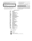
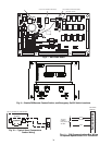
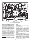
Energy Management Module (Fig. 12) — This
factory-installed option (FIOP) or field-installed accessory is
used for the following types of temperature reset, demand
limit, and/or ice features:
• 4 to 20 mA leaving fluid temperature reset (requires
field-supplied 4 to 20 mA generator)
• 4 to 20 mA cooling set point reset (requires field-
supplied 4 to 20 mA generator)
• Discrete inputs for 2-step demand limit (requires field-
supplied dry contacts capable of handling a 24 vac,
50 mA load)
• 4 to 20 mA demand limit (requires field-supplied 4 to
20 mA generator)
• Discrete input for Ice Done switch (requires field-
supplied dry contacts capable of handling a 24 vac,
50 mA load)
See Demand Limit and Temperature Reset sections on
pages 41 and 37 for further details.
Loss-of-Cooler Flow Protection — A proof-of-
cooler flow device is factory installed in all chillers. It is recom-
mended that proper operation of the switch be verified on a reg-
ular basis.
Electronic Expansion Valves (EXV) — All units are
equipped from the factory with EXVs. Each refrigeration cir-
cuit is also supplied with a factory-installed liquid line filter
drier and sight glass.
The EXV is set at the factory to maintain 9° F (5.0° C) suc-
tion superheat leaving the cooler by metering the proper
amount of refrigerant into the cooler. The superheat set point is
adjustable, but should not be adjusted unless absolutely
necessary.
The EXV is designed to limit the cooler saturated suction
temperature to 50 F (12.8 C). This makes it possible for unit to
start at high cooler fluid temperatures without overloading the
compressor.
Capacity Control — The control system cycles com-
pressors, digital scroll modulting solenoid (if equipped), and
minimum load valve solenoids (if equipped) to maintain the
user-configured leaving chilled fluid temperature set point. En-
tering fluid temperature is used by the main base board (MBB)
to determine the temperature drop across the cooler and is used
in determining the optimum time to add or subtract capacity
stages. The chilled fluid temperature set point can be automati-
cally reset by the return fluid temperature, space, or outdoor-air
temperature reset features. It can also be reset from an external
4 to 20-mA signal (requires energy management module FIOP
or accessory).
The standard control has an automatic lead-lag feature built
in which determines the wear factor (combination of starts and
run hours) for each compressor. If all compressors are off and
less than 30 minutes has elapsed since the last compressor was
turned off, the wear factor is used to determine which
compressor to start next. If no compressors have been running
for more than 30 minutes and the leaving fluid temperature is
greater than the saturated condensing temperature, the wear
factor is still used to determine which compressor to start next.
If the leaving fluid temperature is less than the saturated con-
densing temperature, then the control will start either compres-
sor A1 or compressor B1 first, depending on the user-configu-
rable circuit lead-lag value. For units with the minimum load
control valve, the A circuit with the minimum load valve is al-
ways the lead circuit. The A circuit is also always the lead for
units with the digital compressor option. On units with the dig-
ital scroll option, the A1 compressor operates continuously,
providing close leaving chilled water control. For this reason,
on/off cycling of the unit’s compressors is dramatically re-
duced, which in turn reduces wear associated with compressor
start/stop cycles.
The EXVs will provide a controlled start-up. During start-
up, the low pressure logic will be bypassed for 2
1
/
2
minutes to
allow for the transient changes during start-up. As additional
stages of compression are required, the processor control will
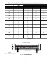
add them. See Table 19.
If a circuit is to be stopped, the compressor with the lowest
wear factor will be shut off first except when a digital compres-
sor is used. The digital compressor is always the last compres-
sor to shut off.
The capacity control algorithm runs every 30 seconds. The
algorithm attempts to maintain the Control Point at the desired
set point. Each time it runs, the control reads the entering and
leaving fluid temperatures. The control determines the rate at
which conditions are changing and calculates 2 variables based
on these conditions. Next, a capacity ratio is calculated using
the 2 variables to determine whether or not to make any
changes to the current stages of capacity. This ratio value
ranges from –100 to +100%. If the next stage of capacity is a
compressor, the control starts (stops) a compressor when the
ratio reaches +100% (–100%). If installed, the minimum load
valve solenoid will be energized with the first stage of capacity.
Minimum load valve value is a fixed 30% in the total capacity
calculation. The control will also use the minimum load valve
solenoid as the last stage of capacity before turning off the last
compressor. A delay of 90 seconds occurs after each capacity
step change. Refer to Table 19.
MINUTES LEFT FOR START — This value is displayed
only in the network display tables (using Service Tool,
ComfortVIEW™ or ComfortWORKS
®
software) and
represents the amount of time to elapse before the unit will start
its initialization routine. This value can be zero without the
machine running in many situations. This can include being
unoccupied, ENABLE/OFF/REMOTE CONTACT switch in
the OFF position, CCN not allowing unit to start, Demand
Limit in effect, no call for cooling due to no load, and alarm or
alert conditions present. If the machine should be running and
none of the above are true, a minimum off time (DELY, see
below) may be in effect. The machine should start normally
once the time limit has expired.
MINUTES OFF TIME (Configuration
OPT2
DELY) — This user-configurable time period is used by the
control to determine how long unit operation is delayed after
power is applied/restored to the unit. Typically, this time period
is configured when multiple machines are located on a single
site. For example, this gives the user the ability to prevent all
the units from restarting at once after a power failure. A value
of zero for this variable does not mean that the unit should be
running.
CAUTION
Care should be taken when interfacing with other manufac-
turer’s control systems due to possible power supply
differences, full wave bridge versus half wave rectification.
The two different power supplies cannot be mixed.
ComfortLink™ controls use half wave rectification. A
signal isolation device should be utilized if a full wave
bridge signal generating device is used.