


103
APPENDIX D — OPTIONAL BACNET COMMUNICATIONS WIRING (cont)
CONFIGURING THE BAS PORT FOR BACNET MS/
TP — Use the same baud rate and communication settings for
all controllers on the network segment. The UPC Open con-
troller is fixed at 8 data bits, No Parity, and 1 Stop bit for this
protocol's communications.
If the UPC Open controller has been wired for power, pull
the screw terminal connector from the controller's power termi-
nals labeled Gnd and HOT. The controller reads the DIP
Switches and jumpers each time power is applied to it.
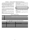
Set the BAS Port DIP switch DS3 to “enable.” Set the BAS
Port DIP switch DS4 to “E1-485.” Set the BMS Protocol DIP
switches DS8 through DS5 to “MSTP.” See Table A.
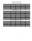
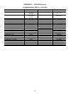
Table A — SW3 Protocol Switch Settings
for MS/TP
Verify that the EIA-485 jumpers below the CCN Port are set
to EIA-485 and 2W.
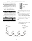
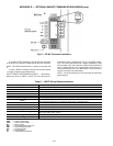
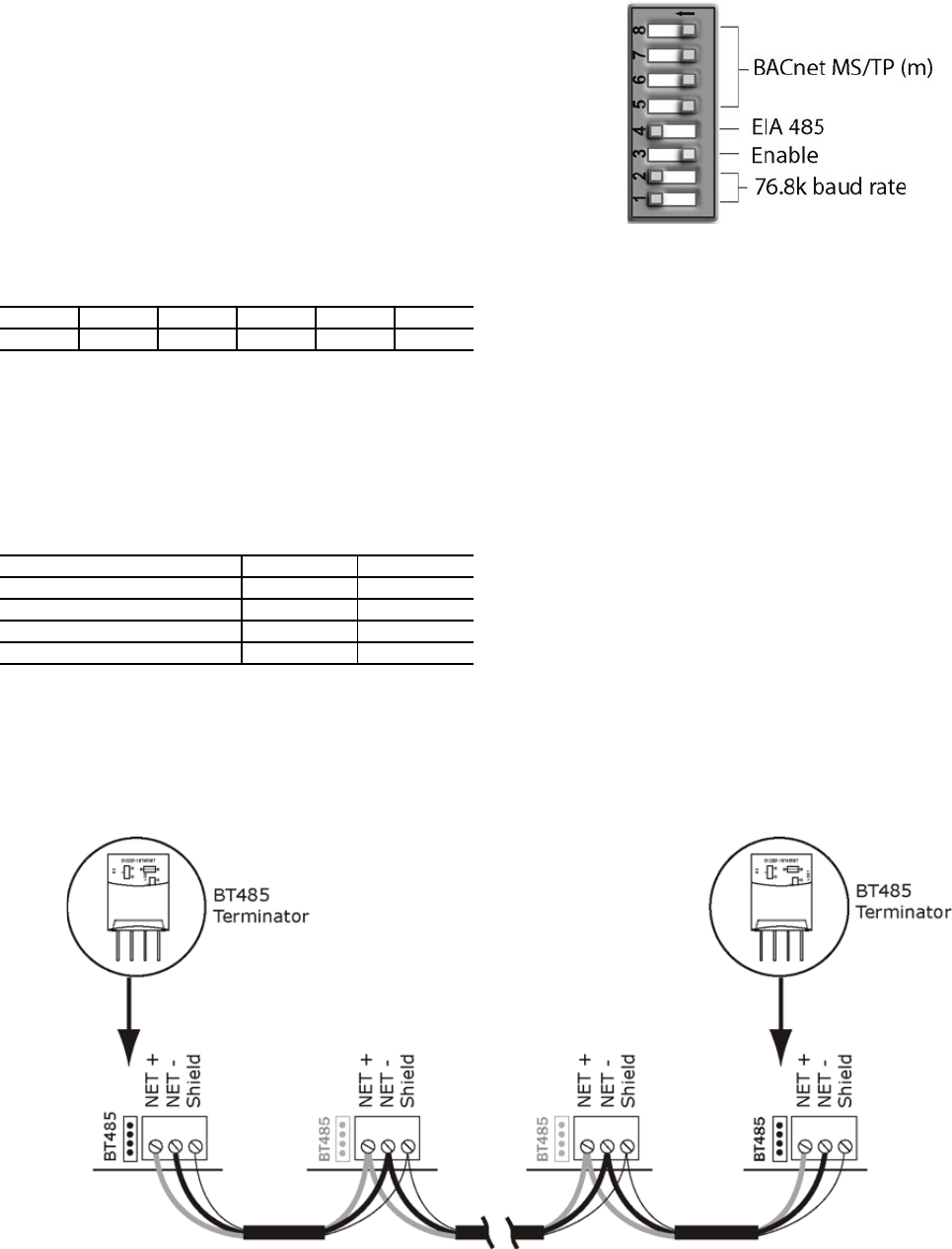
The example in Fig. C shows the BAS Port DIP Switches
set for 76.8k (Carrier default) and MS/TP.
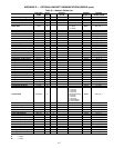
Set the BAS Port DIP Switches DS2 and DS1 for the appro-
priate communications speed of the MS/TP network (9600,
19.2k, 38.4k, or 76.8k bps). See Fig. D and Table B.
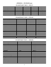
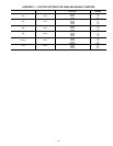
Table B — Baud Selection Table
WIRING THE UPC OPEN CONTROLLER TO THE MS/
TP NETWORK — The UPC Open controller communicates
using BACnet on an MS/TP network segment communications
at 9600 bps, 19.2 kbps, 38.4 kbps, or 76.8 kbps.
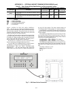
Wire the controllers on an MS/TP network segment in a dai-
sy-chain configuration. Wire specifications for the cable are
22 AWG (American Wire Gage) or 24 AWG, low-capacitance,
twisted, stranded, shielded copper wire. The maximum length
is 2000 ft.
Install a BT485 terminator on the first and last controller on
a network segment to add bias and prevent signal distortions
due to echoing. See Fig. A, D, and E.
To wire the UPC Open controller to the BAS network:
1. Pull the screw terminal connector from the controller's
BAS Port.
2. Check the communications wiring for shorts and
grounds.
3. Connect the communications wiring to the BAS port’s
screw terminals labeled Net +, Net -, and Shield.
NOTE: Use the same polarity throughout the network
segment.
4. Insert the power screw terminal connector into the UPC
Open controller's power terminals if they are not current-
ly connected.
5. Verify communication with the network by viewing a
module status report. To perform a module status report
using the BACview keypad/display unit, press and hold
the “FN” key then press the “.” Key.
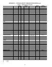
DS8 DS7 DS6 DS5 DS4 DS3
OffOffOffOffOnOff
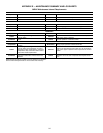
BAUD RATE DS2 DS1
9,600 Off Off
19,200 On Off
38,400 Off On
76,800 On On
Fig. C — DIP Switches
Fig. D — Network Wiring