


53
disconnected from J8. Compare the values determined with the
value read by the control in the Temperatures mode using the
scrolling marquee display.
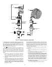
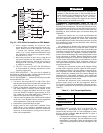
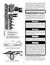
Pressure Transducers — The suction and discharge
transducers are different part numbers and can be distinguished
by the color of the transducer body, suction (yellow) and dis-
charge (red). No pressure transducer calibration is required.
The transducers operate on a 5 vdc supply, which is generated
by the main base board (MBB). See Fig. 29 for transducer con-
nections to the J8 connector on the MBB.
TROUBLESHOOTING — If a transducer is suspected of be-
ing faulty, first check supply voltage to the transducer. Supply
voltage should be 5 vdc ± 0.2 v. If supply voltage is correct,
compare pressure reading displayed on the scrolling marquee
display module against pressure shown on a calibrated pressure
gauge. Pressure readings should be within ± 15 psig. If the
two readings are not reasonably close, replace the pressure
transducer.
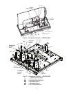
Chilled Water Flow Switch — A factory-installed
flow switch is installed in the leaving fluid piping for all units
without the factory-installed hydronic package. See Fig. 30.
Units with the optional hydronic package have the flow switch
installed in the entering fluid piping. This is a thermal-disper-
sion flow switch with no field adjustments. The switch is set
for approximately 0.5 ft/sec of flow. The sensor tip houses two
thermistors and a heater element. One thermistor is located in
the sensor tip, closest to the flowing fluid. This thermistor is
used to detect changes in the flow velocity of the liquid. The
second thermistor is bonded to the cylindrical wall and is af-
fected only by changes in the temperature of the liquid. The
thermistors are positioned to be in close contact with the wall
of the sensor probe and, at the same time, to be kept separated
from each other within the confines of the probe.
In order to sense flow, it is necessary to heat one of the
thermistors in the probe. When power is applied, the tip of the
probe is heated. As the fluid starts to flow, heat will be carried
away from the sensor tip. Cooling of the first thermistor is a
function of how fast heat is conducted away by the flowing
liquid.
The difference in temperature between the two thermistors
provides a measurement of fluid velocity past the sensor probe.
When fluid velocity is high, more heat will be carried away
from the heated thermistor and the temperature differential will
be small. As fluid velocity decreases, less heat will be taken
from the heated thermistor and there will be an increase in tem-
perature differential.
When unit flow rate is above the minimum flow rate, then
the output is switched on, sending 24 vac to the MBB to prove
flow has been established.
For recommended maintenance, check the sensor tip for
build-up every 6 months. Clean the tip with a soft cloth. If
necessary, build-up (e.g., lime) can be removed with a common
vinegar cleansing agent.
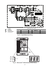
The flow sensor cable is provided with (3) LEDs that indi-
cate if 24 vac power is present and also status of the switch
contacts. The LEDs are as follows:
• Green LED ON – 24 vac present
• One Yellow LED ON – Flow sensor switch OPEN
• Two Yellow LED ON – Flow sensor switch CLOSED
If nuisance trips of the sensor are occurring, follow the
steps below to correct the situation:
1. Check to confirm that the factory installed strainer is
clean. Use the blow-down valve provided or remove the
screen and clean it. For the case of VFD controlled
pumps, ensure that the minimum speed setting has not
been changed.
2. Measure the pressure drop across the cooler or cooler/
pump system and compare this to the system requirements.
3. Verify that cable connections at the switch and at the ter-
minal block are secure.
4. For factory-installed hydronic systems, verify that:
• All air has been purged from the system.
• Circuit setter balance valve has been correctly set.
5. Pump impeller has been improperly trimmed and is not
providing sufficient flow.
6. Wrong pump motor rotation. Pump must rotate clockwise
when viewed from motor end of pump.
Strainer — Periodic factory-installed strainer cleaning is
required. Pressure drop across strainer in excess of 3 psi
(21 kPa) indicates the need for cleaning. Normal (clean) pres-
sure drop is approximately 1 psi (6.9 kPa). Open the factory-
installed blowdown valve to clean the strainer. If required, shut
the chiller down and remove the strainer screen to clean. When
strainer has been cleaned, enter ‘YES’ for Strainer Mainte-
nance Done (Run Status
PM
S.T.MN).
Condenser Fans — Each fan is supported by a formed
wire mount bolted to a fan deck and covered with a wire guard.
METAL FANS — The exposed end of fan motor shaft is pro-
tected from weather by grease and a rubber boot. If fan motor
must be removed for service or replacement, be sure to re-
grease fan shaft and reinstall fan guard. For proper perfor-
mance with the value sound fan option, fan web should be
0.32 in. (8 mm) below top of orifice on the fan deck to top of
the fan hub. (See Fig. 31.) Tighten set screws to 15 ± 1 ft-lb
(20 ± 1.3 N-m).
IMPORTANT: Check for proper fan rotation (clockwise
when viewed from above). If necessary, switch any
2 power leads to reverse fan rotation.
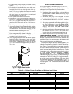
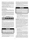
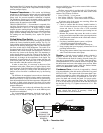
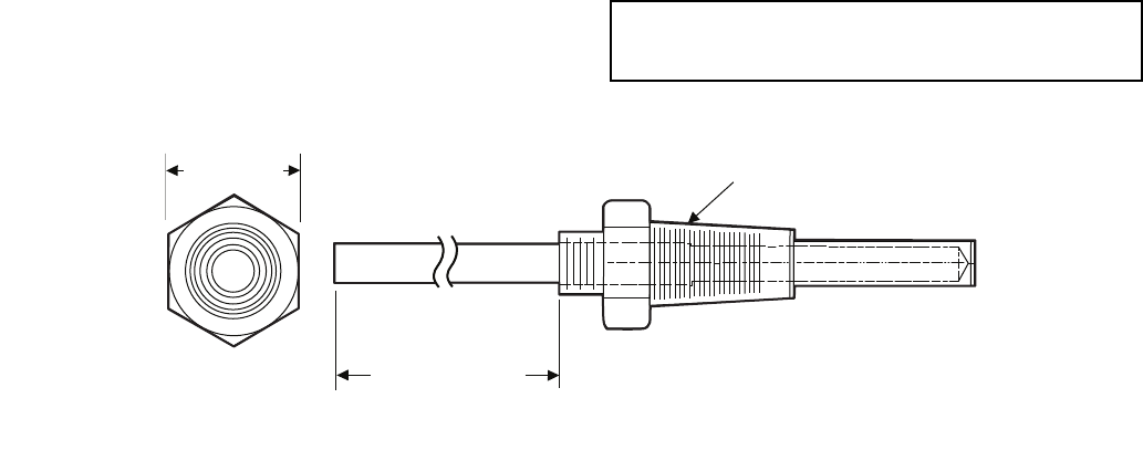
5/8 in. HEX
6" MINIMUM
CLEARANCE FOR
THERMISTOR
REMOVAL
1/4-18 NPT
Fig. 28 — Thermistor Well