


40
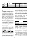
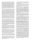
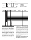
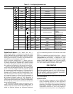
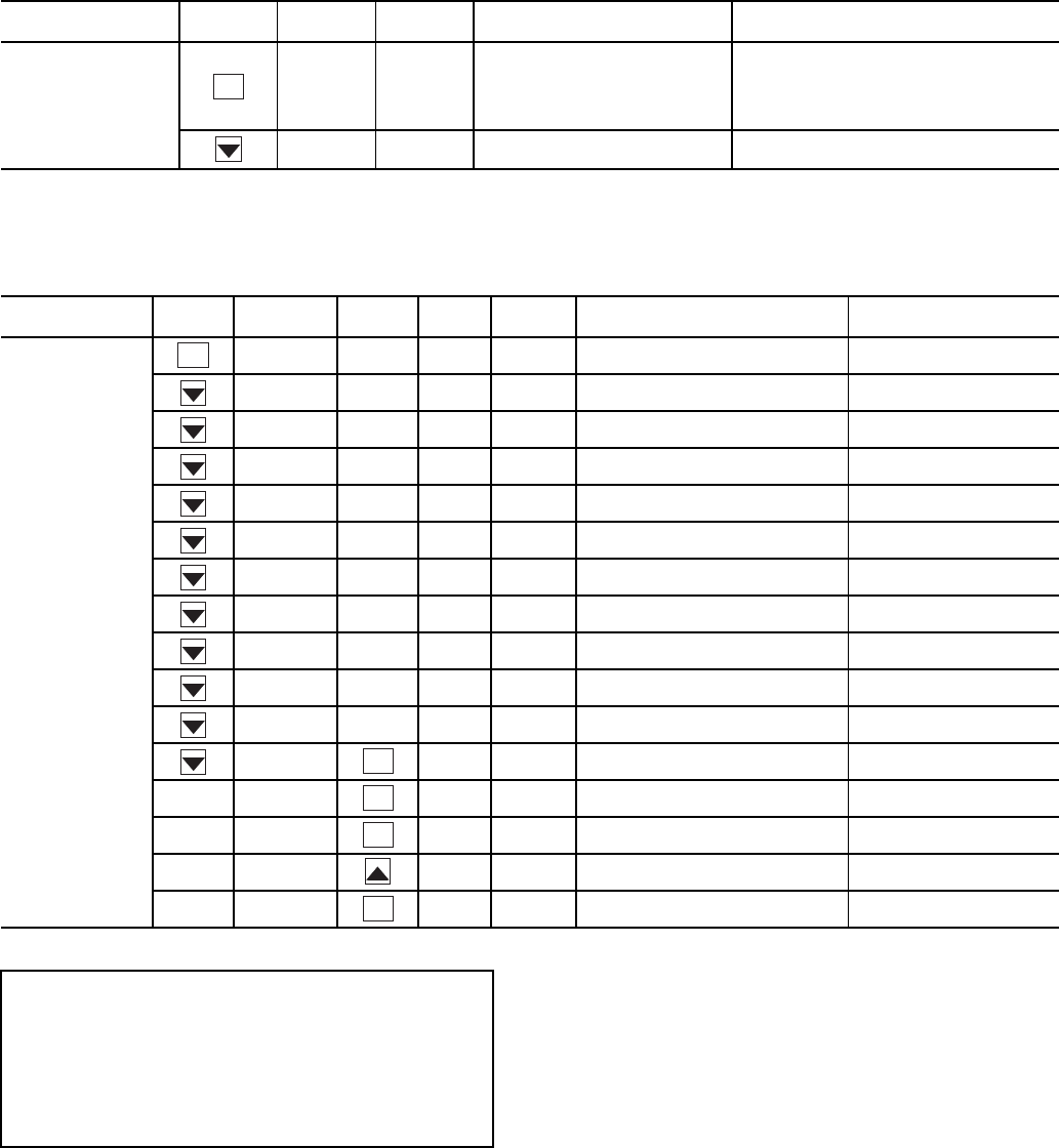
Table 24 — 4 to 20 mA Reset
NOTE: The example above shows how to configure the chiller for 4 to 20 mA reset. No reset will
occur at 4.0 mA input, and a 5.0 F reset will occur at 20.0 mA. An EMM is required.
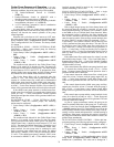
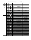
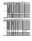
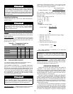
Table 25 — Menu Configuration of 4 to 20 mA Cooling Set Point Control
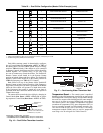
To use outdoor air or space temperature reset, four variables
must be configured. In the Configuration mode under the sub-
mode RSET, items (Configuration
OPT1
CRST), (Con-
figuration
OPT1
RM.NO), (Configuration
OPT1
RM.F), and (Configuration
OPT1
RT.DG) must be
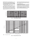
properly set. See Table 26A — Configuring Outdoor Air and
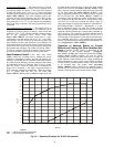
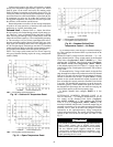
Space Temperature Reset. The outdoor air reset example pro-
vides 0° F (0° C) chilled water set point reset at 85.0 F (29.4 C)
outdoor-air temperature and 15.0 F (8.3 C) reset at 55.0 F
(12.8 C) outdoor-air temperature. The space temperature reset
example provides 0° F (0° C) chilled water set point reset at
72.0 F (22.2 C) space temperature and 6.0 F (3.3 C) reset at
68.0 F (20.0 C) space temperature. The variable CRST should
be configured for the type of reset desired. The variable
RM.NO should be set to the temperature that no reset should
occur. The variable RM.F should be set to the temperature that
maximum reset is to occur. The variable RM.DG should be set
to the maximum amount of reset desired. Figures 18 and 19 are
examples of outdoor air and space temperature resets.
To use return reset, four variables must be configured. In the
Configuration mode under the sub-mode RSET, items CRST,
RT.NO, RT.F and RT.DG must be properly set. See Table 26B
— Configuring Return Temperature Reset. This example pro-
vides 5.0 F (2.8 C) chilled water set point reset at 2.0 F (1.1 C)
cooler T and 0° F (0° C) reset at 10.0 F (5.6 C) cooler T. The
variable RT.NO should be set to the cooler temperature differ-
ence (T) where no chilled water temperature reset should oc-
cur. The variable RT.F should be set to the cooler temperature
difference where the maximum chilled water temperature reset
should occur. The variable RM.DG should be set to the maxi-
mum amount of reset desired.
To verify that reset is functioning correctly proceed to Run
Status mode, sub-mode VIEW, and subtract the active set point
(Run Status
VIEW
SETP) from the control point (Run
Status
VIEW
CTPT) to determine the degrees reset.
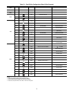
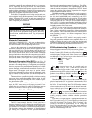
SUB-MODE
KEYPAD
ENTRY
ITEM DISPLAY
ITEM
EXPANSION
COMMENT
RSET
CRST 1
COOLING RESET
TYPE
0 = no reset
1 = 4 to 20 mA input
2 = Outdoor air temp
3 = Return Fluid
4 = Space Temperature
MA.DG
5.0 F
(2.8 C)
DEGREES COOL
RESET
Default: 0° F (0° C) Reset at 20 mA
Range: –30 to 30 F (–16.7 to 16.7 C)
MODE
(RED LED)
KEYPAD
ENTRY
SUB-MODE
KEYPAD
ENTRY
ITEM DISPLAY
ITEM
EXPANSION
COMMENT
CONFIGURATION
DISP
UNIT
OPT1
OPT2
HP.A
HP.B
EXV.A
EXV.B
M.MST
RSET
DMDC
SLCT CLSP 0 COOLING SETPOINT SELECT
0 Scrolling Stops
0 Flashing ‘0’
4Select ‘4’
4 Change Accepted
ENTER
ENTER
ENTER
ENTER
ENTER
ENTER
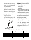
IMPORTANT: Care should be taken when interfacing with
other control systems due to possible power supply differ-
ences: full wave bridge versus half wave rectification. Con-
nection of control devices with different power supplies
may result in permanent damage. ComfortLink™ controls
incorporate power supplies with half wave rectification. A
signal isolation device should be utilized if the signal gen-
erator incorporates a full wave bridge rectifier.