


18
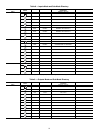
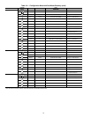
Table 14 — Operating Modes
MODE
NO.
ITEM EXPANSION DESCRIPTION
01 CSM CONTROLLING CHILLER Chillervisor System Manager (CSM) is controlling the chiller.
02 WSM CONTROLLING CHILLER Water System Manager (WSM) is controlling the chiller.
03 MASTER/SLAVE CONTROL Dual Chiller control is enabled.
05
RAMP LOAD LIMITED Ramp load (pull-down) limiting in effect. In this mode, the rate at which leaving fluid temperature
is dropped is limited to a predetermined value to prevent compressor overloading. See Cooling
Ramp Loading (Configuration
SLCT
CRMP). The pull-down limit can be modified, if
desired, to any rate from 0.2° F to 2° F (0.1° to 1° C)/minute.
06
TIMED OVERRIDE IN EFFECT Timed override is in effect. This is a 1 to 4 hour temporary override of the programmed
schedule, forcing unit to Occupied mode. Override can be implemented with unit under
Local (Enable) or CCN (Carrier Comfort Network
®
) control. Override expires after each use.
07
LOW COOLER SUCTION TEMPA Circuit A cooler Freeze Protection mode. At least one compressor must be on, and the Sat-
urated Suction Temperature is not increasing greater than 1.1° F (0.6° C) in 10 seconds. If
the saturated suction temperature is less than the Brine Freeze Point (Set Points
FRZ
BR.FZ) minus 6° F (3.4° C) and less than the leaving fluid temperature minus 14° F
(7.8° C) for 2 minutes, a stage of capacity will be removed from the circuit. Or, If the satu-
rated suction temperature is less than the Brine Freeze Point minus 14° F (7.8° C), for
90 seconds, a stage of capacity will be removed from the circuit. The control will continue to
decrease capacity as long as either condition exists.
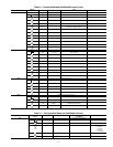
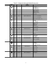
08
LOW COOLER SUCTION TEMPB Circuit B cooler Freeze Protection mode. At least one compressor must be on, and the Sat-
urated Suction Temperature is not increasing greater than 1.1° F (0.6° C) in 10 seconds. If
the saturated suction temperature is less than the Brine Freeze Point (Set Points
FRZ
BR.FZ) minus 6° F (3.4° C) and less than the leaving fluid temperature minus 14° F
(7.8° C) for 2 minutes, a stage of capacity will be removed from the circuit. Or, If the satu-
rated suction temperature is less than the Brine Freeze Point minus 14° F (7.8° C), for
90 seconds, a stage of capacity will be removed from the circuit. The control will continue to
decrease capacity as long as either condition exists.
09
SLOW CHANGE OVERRIDE Slow change override is in effect. The leaving fluid temperature is close to and moving
towards the control point.
10 MINIMUM OFF TIME ACTIVE Chiller is being held off by Minutes Off Time (Configuration
OPT2
DELY).
13
DUAL SETPOINT Dual Set Point mode is in effect. Chiller controls to Cooling Set Point 1 (Set Points
COOL
CSP.1) during occupied periods and Cooling Set Point 2 (Set Points
COOL
CSP.2)
during unoccupied periods.
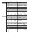
14
TEMPERATURE RESET Temperature reset is in effect. In this mode, chiller is using temperature reset to adjust leav-
ing fluid set point upward and is currently controlling to the modified set point. The set point
can be modified based on return fluid, outdoor-air-temperature, space temperature, or 4 to
20 mA signal.
15
DEMAND/SOUND LIMITED Demand limit is in effect. This indicates that the capacity of the chiller is being limited by
demand limit control option. Because of this limitation, the chiller may not be able to pro-
duce the desired leaving fluid temperature. Demand limit can be controlled by switch inputs
or a 4 to 20 mA signal.
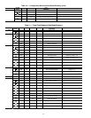
16
COOLER FREEZE PROTECTION Cooler fluid temperatures are approaching the Freeze point (see Alarms and Alerts section
for definition). The chiller will be shut down when either fluid temperature falls below the
Freeze point.
17
LOW TEMPERATURE COOLING Chiller is in Cooling mode and the rate of change of the leaving fluid is negative and
decreasing faster than -0.5° F per minute. Error between leaving fluid and control point
exceeds fixed amount. Control will automatically unload the chiller if necessary.
18
HIGH TEMPERATURE COOLING Chiller is in Cooling mode and the rate of change of the leaving fluid is positive and increasing.
Error between leaving fluid and control point exceeds fixed amount. Control will automatically
load the chiller if necessary to better match the increasing load.
19
MAKING ICE Chiller is in an unoccupied mode and is using Cooling Set Point 3 (Set Points
COOL
CSP.3) to make ice. The ice done input to the Energy Management Module (EMM) is open.
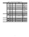
20
STORING ICE Chiller is in an unoccupied mode and is controlling to Cooling Set Point 2 (Set Points
COOL
CSP.2). The ice done input to the Energy Management Module (EMM) is closed.
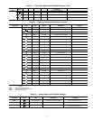
21
HIGH SCT CIRCUIT A Chiller is in a Cooling mode and the Saturated Condensing Temperature (SCT) is greater than
the calculated maximum limit. No additional stages of capacity will be added. Chiller capacity
may be reduced if SCT continues to rise to avoid high-pressure switch trips by reducing con-
densing temperature.
22
HIGH SCT CIRCUIT B Chiller is in a Cooling mode and the Saturated Condensing Temperature (SCT) is greater than
the calculated maximum limit. No additional stages of capacity will be added. Chiller capacity
may be reduced if SCT continues to rise to avoid high-pressure switch trips by reducing con-
densing temperature.
23
MINIMUM COMP ON TIME Cooling load may be satisfied, however control continues to operate compressor to ensure
proper oil return. May be an indication of oversized application, low fluid flow rate or low loop
volume.
24
PUMP OFF DELAY TIME Cooling load is satisfied, however cooler pump continues to run for the number of minutes set
by the configuration variable Cooler Pump Shutdown Delay (Configuration
OPT1
PM.DY).
25
LOW SOUND MODE Chiller operates at higher condensing temperature and/or reduced capacity to minimize
overall unit noise during evening/night hours (Configuration
OPT2
LS.MD).