


38
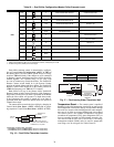
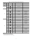
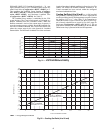
Table 22 — Dual Chiller Configuration (Master Chiller Example) (cont)
NOTES:
1. Master Control Method (CTRL) can be configured as 0-Switch, 2-Occupancy or 3-CCN.
2. Parallel Configuration (PARA) cannot be changed.
Dual chiller start/stop control is determined by configura-
tion of Control Method (Configuration
OPT1
CTRL) of
the Master chiller. The Slave chiller should always be config-
ured for CTRL=0 (Switch). If the chillers are to be controlled
by Remote Contacts, both Master and Slave chillers should be
enabled together. Two separate relays or one relay with
two sets of contacts may control the chillers. The Enable/Off/
Remote Contact switch should be in the Remote Contact
position on both the Master and Slave chillers. The Enable/Off/
Remote Contact switch should be in the Enable position for
CTRL=2 (Occupancy) or CTRL=3 (CCN Control).
Both chillers will stop if the Master chiller Enable/Off/
Remote Contact switch is in the Off position. If the Emergency
Stop switch is turned off or an alarm is generated on the Master
chiller the Slave chiller will operate in a Stand-Alone mode.
If the Emergency Stop switch is turned off or an alarm is
generated on the Slave chiller the Master chiller will operate in
a Stand-Alone mode.
The master chiller controls the slave chiller by changing its
Control Mode (Run Status
VIEW
STAT) and its operat-
ing setpoint or Control Point (Run Status
VIEW
CT.PT).
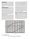
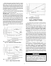
Temperature Reset — The control system is capable of
handling leaving-fluid temperature reset based on return cooler
fluid temperature. Because the change in temperature through
the cooler is a measure of the building load, the return tempera-
ture reset is in effect an average building load reset method.
The control system is also capable of temperature reset based
on outdoor-air temperature (OAT), space temperature (SPT), or
from an externally powered 4 to 20 mA signal. Accessory sen-
sors must be used for SPT reset (33ZCT55SPT). The energy
management module (EMM) must be used for temperature
reset using a 4 to 20 mA signal. See Tables 24 and 25.
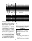
SUB-MODE ITEM KEYPAD ENTRY DISPLAY ITEM EXPANSION COMMENTS
RSET
LLBL 2 LEAD/LAG BALANCE SELECT CHANGE ACCEPTED
LLBL
LLBD LEAD/LAG BALANCE DELTA
LLBD 168 LEAD/LAG BALANCE DELTA DEFAULT 168
LLBD
LLDY LAG START DELAY
LLDY 5 SCROLLING STOPS
5 VALUE FLASHES
10 SELECT 10
LLDY 10 LAG START DELAY CHANGE ACCEPTED
LLDY
RSET
PARA YES MASTER COMPLETE
ENTER
ESCAPE
ENTER
ESCAPE
ENTER
ENTER
ENTER
ESCAPE
ESCAPE
ENTER
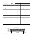
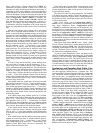
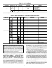
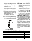
MASTER
CHILLER
SLAVE
CHILLER
LEAVING
FLUID
RETURN
FLUID
THERMISTOR
WIRING*
INSTALL DUAL CHILLER LWT
LEAVING FLUID TEMPERATURE
THERMISTOR (T10) HERE
*Depending on piping sizes, use either:
• HH79NZ014 sensor/10HB50106801 well (3-in. sensor/well)
• HH79NZ029 sensor/10HB50106802 well (4-in. sensor/well)
Fig. 16 — Dual Chiller Thermistor Location
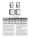
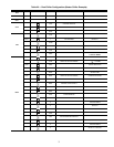
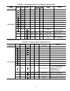
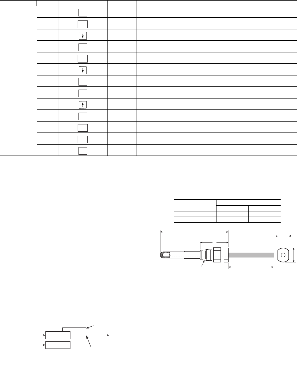
A
B
1/4 N.P.T.
0.505/0.495
0.61
DIA
6” MINIMUM
CLEARANCE FOR
THERMISTOR
REMOVAL
Fig. 17 — Dual Leaving Water Thermistor Well
PART
NUMBER
DIMENSIONS in. (mm)
A B
10HB50106801 3.10 (78.7) 1.55 (39.4)
10HB50106802 4.10 (104.1) 1.28 (32.5)