


44
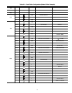
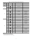
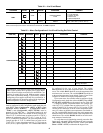
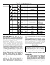
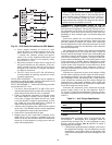
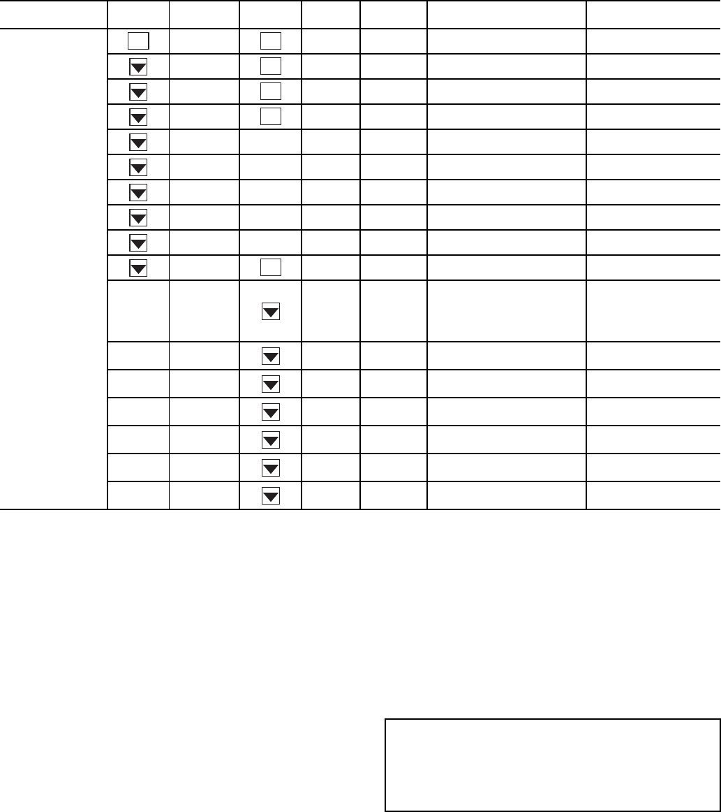
Table 27 — Configuring Demand Limit
*Seven items skipped in this example.
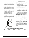
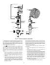
Digital Scroll Option — The 30RAP units have a
factory-installed option for a digital scroll compressor which
provides additional stages of unloading for the unit. The digital
compressor is always installed in the A1 compressor location.
When a digital compressor is installed, a digital unloader sole-
noid (DUS) is used on the digital compressor.
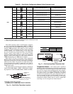
DIGITAL SCROLL OPERATION — A digital scroll oper-
ates in two stages - the "loaded state" when the solenoid valve
is normally closed and the "unloaded state" when the solenoid
valve is open. During the loaded state, the compressor operates
like a standard scroll and delivers full capacity and mass flow.
However, during the unloaded state, there is no capacity
and no mass flow through the compressor. The capacity of the
system is varied by varying the time the compressor operates
in an unloaded and loaded state during a 15-second period. If
the DUS is energized for 7 seconds, the compressor will be
operating at 47% capacity. If the DUS is energized for 10 sec-
onds, the compressor will be operating at approximately 33%
of its capacity. Capacity is the time averaged summation of
loaded and unloaded states, and its range is continuous from
the minimum configured capacity to 100%. Regardless of
capacity, the compressor always rotates with constant speed.
As the compressor transitions from a loaded to unloaded state,
the discharge and suction pressures will fluctuate and the com-
pressor sound will change.
The ComfortLink controller controls and integrates the op-
eration of the DUS into the compressor staging routine to
maintain temperature control. When a digital compressor is in-
stalled, an additional discharge gas temperature thermistor
(DTT) is installed along with the AUX board for control of the
DUS.
DIGITAL COMPRESSOR CONFIGURATION — When a
digital compressor is installed, the configuration parameter
(Configuration
UNIT
A1TY) is configured to YES.
There is also a maximum unload time configuration, (Config-
uration
UNIT
MAX.T) that is set to 7 seconds, which in-
dicates the maximum unloading for the digital compressor is
47%. This is done to optimize efficiency of the system.
PRE-START-UP
Do not attempt to start the chiller until following checks
have been completed.
System Check
1. Check all auxiliary components, such as chilled fluid
pumps, air-handling equipment, or other equipment to
which the chiller supplies liquid. Consult manufacturer's
instructions. Verify that any pump interlock contacts have
been properly installed. If the unit If the unit has
field-installed accessories, be sure all are properly in-
stalled and wired correctly. Refer to unit wiring diagrams.
MODE
KEYPAD
ENTRY
SUB-MODE
KEYPAD
ENTRY
ITEM DISPLAY ITEM EXPANSION COMMENT
CONFIGURATION
DISP TEST ON/OFF Test Display LEDs
UNIT TYPE X Unit Type
OPT1 FLUD X Cooler Fluid
OPT2 CTRL X Control Method
HP.A
HP.B
EXV.A
EXV.B
M.MST
RSET CRST X Cooling Reset Type
DMDC* X Demand Limit Select
Default: 0
0 = None
1 = Switch
2 = 4 to 20 mA Input
3 = CCN Loadshed
DM20 XXX % Demand Limit at 20 mA
Default: 100%
Range: 0 to 100
SHNM XXX
Loadshed Group
Number
Default: 0
Range: 0 to 99
SHDL XXX%
Loadshed Demand
Delta
Default: 0%
Range: 0 to 60%
SHTM XXX MIN
Maximum Loadshed
Time
Default: 60 min.
Range: 0 to 120 min.
DLS1 XXX %
Demand Limit
Switch 1
Default: 80%
Range: 0 to 100%
DLS2 XXX %
Demand Limit
Switch 2
Default: 50%
Range: 0 to 100%
ENTER
ENTER
ENTER
ENTER
ENTER
ENTER
IMPORTANT: Before beginning Pre-Start-Up or Start-Up,
complete Start-Up Checklist for 30RAP Liquid Chiller at
end of this publication (pages CL-1 to CL-10). The check-
list assures proper start-up of a unit, and provides a record
of unit condition, application requirements, system infor-
mation, and operation at initial start-up.