


36
(Pump 1 Starts First) or 2 (Pump 2 Starts First). If PM.SL is 0
(Automatic), the pump selection is based on two criteria: the
alert status of a pump and the operational hours on the pump. If
a pump has an active Alert condition, it will not be considered
for the lead pump. The pump with the lowest operational hours
will be the lead pump. A pump is selected by the control to start
and continues to be the lead pump until the Pump Changeover
Hours (Configuration
OPT1
PM.DT) is reached. The
Lead Pump (Run Status
VIEW
LD.PM) indicates the
pump that has been selected as the lead pump: 1 (Pump 1), 2
(Pump 2), 3 (No Pump). The Pump Changeover Hours is facto-
ry defaulted to 500 hours. Regardless of the Cooler Pump Se-
lection, any pump that has an active alert will not be allowed to
start.
With the dual integral pump package, the Cooler Pump
Starter will be energized when the machine is in an occupied
period. As part of the factory-installed package, an auxiliary set
of contacts is wired to the MBB to serve as Chilled Water Pump
Interlock, one set for each pump to individual channels on the
MBB. With a call for mechanical cooling, the specific pump
interlock and flow switch are checked. If the circuits are closed,
the machine starts its capacity routine. If Pump 1 starts and the
auxiliary contact interlock does not close within 25 seconds of
the ON command, a T190 — Cooler Pump 1 Aux Contacts
Failed to Close at Start-Up Alert will be generated and the
pump shut down. The unit will not be allowed to start. If the
chilled water flow switch does not close within 1 minute, two
alarms will be generated. A T192 — Cooler Pump 1 Failed to
Provide Flow at Start-Up Alert and an A200 — Cooler Flow/
Interlock Failed to Close at Start-Up Alarm will be generated
and chiller will not be allowed to start. In either fault case listed
above, Pump 2 will be commanded to start once Pump 1 has
failed.
If Pump 2 starts and the auxiliary contact interlock does
not close within 25 seconds of the ON command, a T191 —
Cooler Pump 2 Aux Contacts Failed to Close at Start-Up Alert
will be generated and the pump shut down. The unit will not be
allowed to start. If the chilled water flow switch does not close
within one (1) minute, two alarms will be generated. A T193
— Cooler Pump 2 Failed to Provide Flow at Start-Up Alert and
an A200 — Cooler Flow/Interlock Failed to Close at Start-Up
Alarm will be generated and chiller will not be allowed to start.
In either fault case listed above, Pump 1 will be commanded to
start once Pump 2 has failed.
If the chilled water flow switch opens for at least 3 seconds
after initially being closed, a T196 — Flow Lost While Pump 1
Running Alert or T197 — Flow Lost While Pump 2 Running
Alert for the appropriate pump and an A201 — Cooler Flow/
Interlock Contacts Opened During Normal Operation Alarm
will be generated and the machine will stop. If available, the
other pump will be started. If flow is proven, the machine will
be allowed to restart.
If the chilled water pump interlock opens for 25 seconds
after initially being closed is detected by the control, the appro-
priate T194 — Cooler Pump 1 Contacts Opened During Nor-
mal Operation Alert or T195 — Cooler Pump 2 Contacts
Opened During Normal Operation Alert is generated and the
unit is shut down. If available, the other pump will be started. If
flow is proven, the machine will be allowed to restart.
If the control detects that the chilled water flow switch
circuit is closed for at least 5 minutes with the pump output
OFF, an A202 — Cooler Pump Interlock Closed When Pump
is Off Alarm will be generated and the unit will not be allowed
to start.
If the control detects that the chilled water pump auxiliary
contacts are closed for at least 25 seconds while the pump is
OFF, the appropriate T198 — Cooler Pump 1 Aux Contacts
Closed While Pump Off or Alert T199 — Cooler Pump 2 Aux
Contacts Closed While Pump Off Alert is generated. The
chiller will not be allowed to start.
If the control starts a pump and the wrong interlock circuit
closes for at least 20 seconds, an A189 – Cooler Pump and Aux
Contact Input Miswire Alarm will be generated. The unit will
be prevented from starting.
The control will allow for pump changeover. Two methods
will change the pump sequence. Before the changeover can
occur, the unit must be at Capacity Stage 0. During changeover
the chilled water flow switch input is ignored for 10 seconds to
avoid a nuisance alarm.
With Cooler Pump Select (Configuration
OPT1
PM.SL) set to 0 (Automatic) and when the differential time
limit Pump Changeover Hours (Configuration
OPT1
PM.DT) is reached, the lead pump will be turned OFF. Ap-
proximately one (1) second later, the lag pump will start. Manu-
al changeover can be accomplished by changing Rotate Cooler
Pump Now (Configuration
OPT1
ROT.P) to YES only if
the machine is at Capacity Stage 0 and the differential time limit
Pump Changeover Hours (PM.DT) is reached. If the PM.DT is
not satisfied, the changeover will not occur. With the machine at
Capacity Stage 0, the pumps would rotate automatically as part
of the normal routine.
With Cooler Pump Select (PM.SL) set to 1 (Pump 1 Starts
First) or 2 (Pump 2 Starts First), a manual changeover can be ac-
complished by changing PM.SL only. The machine Remote-
Off-Enable Switch must be in the OFF position to change this
variable. The Rotate Cooler Pump Now (ROT.P) feature does
not work for these configuration options.
As part of a pump maintenance routine, the pumps can be
started to maintain lubrication to the pump seal. To utilize this
function, Cooler Pmp Periodic Start (Configuration
OPT1
PM.PS) must be set to YES. This option is set to NO as the
factory default. If feature is enabled and the pump(s) are not
operating, then the pumps will be operated every other day for
2 seconds starting at 14:00 hours. If a pump has failed and has
an active Alert condition, it will not be started that day.
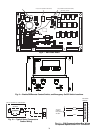
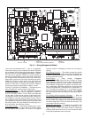
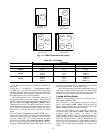
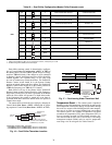
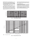
Configuring and Operating Dual Chiller Con-
trol — The dual chiller routine is available for the control of
two units supplying chilled fluid on a common loop. This
control algorithm is designed for parallel fluid flow arrangement
only. One chiller must be configured as the master chiller, the
other as the slave. An additional leaving fluid temperature
thermistor (Dual Chiller LWT) must be installed as shown in
Fig. 16 and 17 and connected to the master chiller. Refer to Sen-
sors section, page 20, for wiring. The CCN communication bus
must be connected between the two chillers. Connections can be
made to the CCN screw terminals on LVT. Refer to Carrier
Comfort Network
®
Interface section, page 19, for wiring infor-
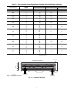
mation. Configuration examples are shown in Tables 22 and 23.
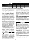
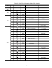
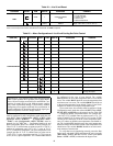
Refer to Table 22 for dual chiller configuration. In this
example the master chiller will be configured at address 1 and
the slave chiller at address 2. The master and slave chillers
must reside on the same CCN bus (Configuration
CCN
CCNB) but cannot have the same CCN address (Configu-
ration
CCN
CCNA). Both master and slave chillers must
have Lead/Lag Chiller Enable (Configuration
RSET
LLEN) configured to ENBL. Master/Slave Select (Config-
uration
RSET
MSSL) must be configured to MAST for
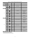
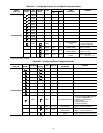
the master chiller and SLVE for the slave. Also in this example,
the master chiller will be configured to use Lead/Lag Balance
Select (Configuration
RSET
LLBL) and Lead/Lag Bal-
ance Delta (Configuration
RSET
LLBD) to even out the
chiller run-times weekly. The Lag Start Delay (Configura-
tion
RSET
LLDY) feature will be set to 10 minutes. This
will prevent the lag chiller from starting until the lead chiller
has been at 100% capacity for the length of the delay time. Par-
allel configuration (Configuration
RSET
PARA) can
only be configured to YES. The variables LLBL, LLBD and
LLDY are not used by the slave chiller.