


31
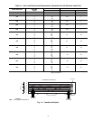
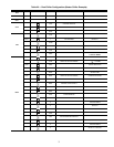
Table 19 — Part Load Data Percent Displacement, Standard Units with Minimum Load Valve
*Minimum Load Valve energized. NOTE: These capacity steps may vary due to different capacity
staging sequences.
30RAP UNIT SIZE
CONTROL
STEPS
CAPACITY STEPS CAPACITY %
% Displacement Circuit A Circuit B
010 1 100100—
015 1 100100—
018
1
2
3
100
50
20*
100 —
020
1
2
3
100
50
24*
100 —
025
1
2
3
100
50
29*
100 —
030
1
2
3
100
50
32*
100 —
035
1
2
3
4
5
100
77
50
23
9*
54 46
040
1
2
3
4
5
100
73
50
23
11*
47 53
045
1
2
3
4
5
100
74
50
24
12*
47 53
050
1
2
3
4
5
100
75
50
25
14*
50 50
055
1
2
3
4
5
100
73
50
23
13*
46 54
060
1
2
3
4
5
100
75
50
25
16*
50 50
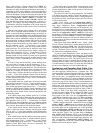
47
46
45
44
43
42
41
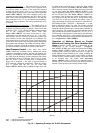
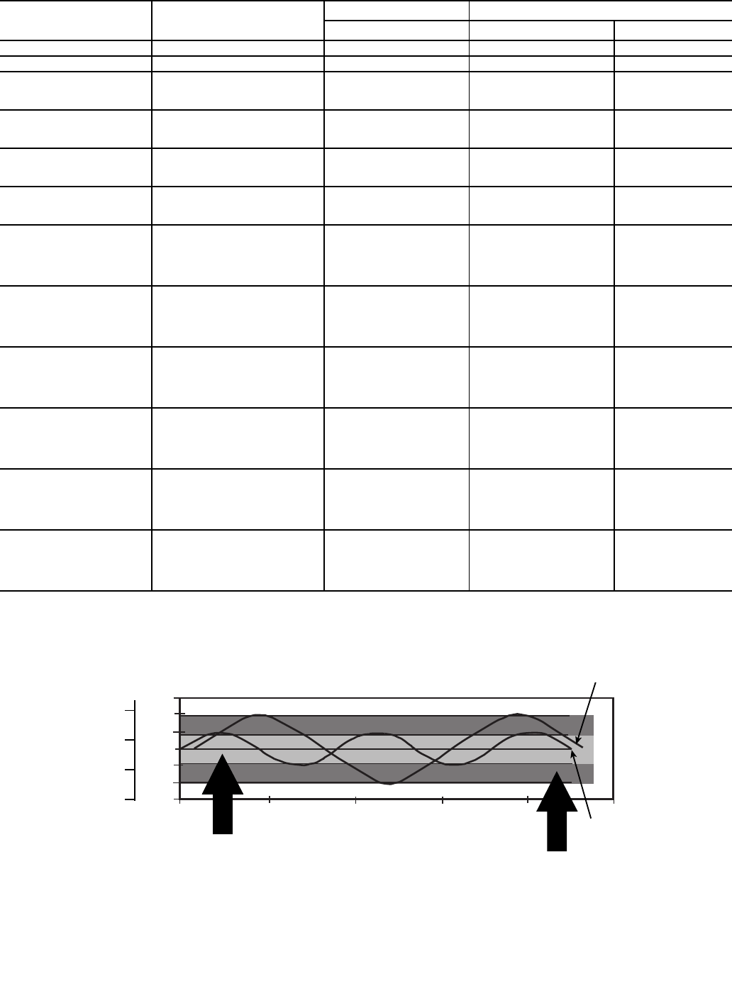
0 200 400 600 800 1000
TIME (SECONDS)
2 STARTS
3 STARTS
DEADBAND EXAMPLE
LWT (F)
MODIFIED
DEADBAND
STANDARD
DEADBAND
8
7
6
5
LWT (C)
LEGEND
LWT — Leaving Water Temperature
Fig. 13 — Deadband Multiplier