


21
Units on the CCN can be monitored from the space at the
sensor through the RJ11 connector, if desired. To wire the RJ11
connector into the CCN (Fig. 11):
1. Cut the CCN wire and strip ends of the red (+), white
(ground), and black (–) conductors. (If another wire color
scheme is used, strip ends of appropriate wires.)
2. Insert and secure the red (+) wire to terminal 5 of the
space temperature sensor terminal block.
3. Insert and secure the white (ground) wire to terminal 4 of
the space temperature sensor.
4. Insert and secure the black (–) wire to terminal 2 of the
space temperature sensor.
5. Connect the other end of the communication bus cable to
the remainder of the CCN communication bus.
Dual Leaving Water Temperature Sensor
— For dual chiller
applications (parallel only are supported), connect the dual
chiller leaving fluid temperature sensor (refer to Configuring
and Operating Dual Chiller Control section on page 36) to the
space temperature input of the Master chiller. If space tempera-
ture is required for reset applications, connect the sensor to the
Slave chiller and configure the slave chiller to broadcast the
value to the Master chiller.
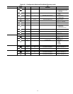
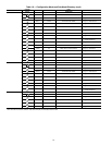
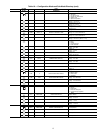
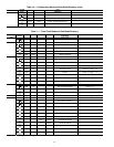
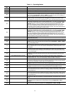
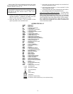
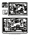
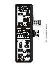
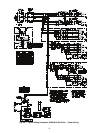
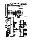
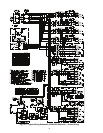
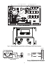
LEGEND FOR FIG. 3-7
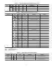
IMPORTANT: The cable selected for the RJ11 connector
wiring MUST be identical to the CCN communication bus
wire used for the entire network. Refer to Table 18 for
acceptable wiring.
ALMR — Alarm Relay
AUX — Auxilliary
BR — Boiler Relay
C—Contactor, Compressor
CB — Circuit Breaker
CCB — Compressor Circuit Breaker
CH — Crankcase Heater
CHC — Cooler/Pump Heater Contactor
COMP — Compressor
CSB — Current Sensor Board
CWFS — Chilled Water Flow Switch
CWP — Chilled Water Pump
DGS — Digital Scroll Compressor
DPT — Discharge Pressure Transducer
DTT — Discharge Temperature Thermistor
DUS — Digital Unloader Solenoid
EMM — Energy Management
EXV — Electronic Expansion Valve
FB — Fuse Block
FC — Fan Contactor
FCB — Fan Circuit Breaker
FIOP — factory Installed Option
FR — Fan Relay
GND — Ground
HPS — High-Pressure Switch
LON — Local Operating Network
LVT — Low Voltage Terminal Block
MBB — Main Base Board
MLV — Minimum Load Valve
MM — Motormaster
MP — Motor Protector
MS — Manual Starter
NEC — National Electrical Code
OAT — Outdoor-Air Thermistor
OFM — Outdoor Fan Motor
RGT — Return Gas Thermistor
SCCR — Short Circuit Current Rating
SPT — Suction Pressure Transducer
SW — Switch
TB — Terminal Block
TNKR — Storage Tank Heater Relay
TRAN — Transformer
UPC — Unitary Protocol Converter
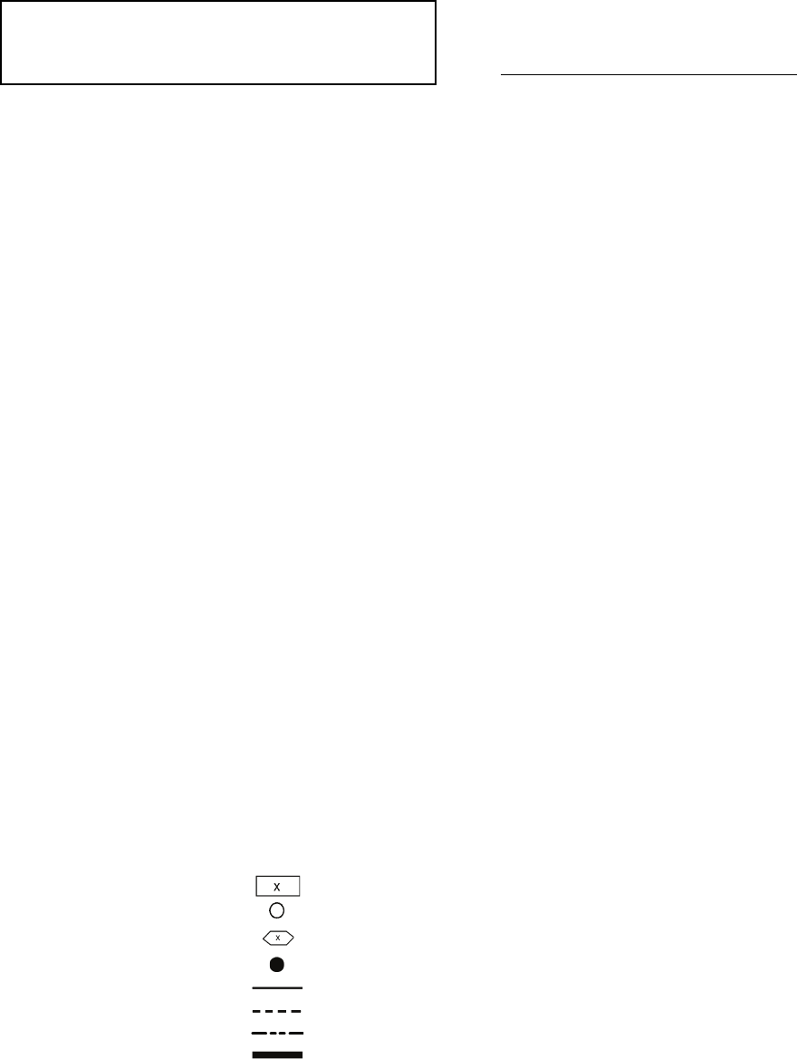
Terminal Block
Terminal (Unmarked)
Terminal (Marked)
Splice
Factory Wiring
Field Wiring
Accessory or Option Wiring
To indicate common potential only; not to represent wiring.