


35
Cooler Pump Sequence of Operation — At any-
time the unit is in an ON status, as defined by the one of the
following conditions, the cooler pump relay will be enabled.
1. The Enable-Off-Remote Switch in ENABLE,
(CTRL=0).
2. Enable-Off-Remote Switch in REMOTE with a
Start-Stop remote contact closure (CTRL=0).
3. An Occupied Time Period from an Occupancy Schedule
in combination with items 1 or 2 (CTRL=2).
4. A CCN Start-Stop Command to Start in combination
with items 1 or 2 (CTRL=3).
As stated before, there are certain alarm conditions and
Operating Modes that will turn the cooler pump relay ON. This
sequence will describe the normal operation of the pump
control algorithm.
When the unit cycles from an “On” state to an “Off” state,
the cooler pump output will remain energized for the Cooler
Pump Shutdown Delay (Configuration
OPT1
PM.DY).
This is configurable from 0 to 10 minutes. The factory default
is 1 minute.
NO INTEGRAL PUMP — SINGLE EXTERNAL PUMP
CONTROL — With a single external pump, the following
options must be configured:
• Cooler Pump Control (Configuration
OPT1
CPC) =
OFF.
• Cooler Pump 1 Enable (Configuration
OPT1
PM1E) = NO.
• Cooler Pump 2 Enable (Configuration
OPT1
PM2E) = NO.
The maximum load allowed for the Chilled Water Pump
Starter is 5 VA sealed, 10 VA inrush at 24 volts. The starter coil
is powered from the chiller control system. The starter should
be wired between LVT-25 and LVT-21. If equipped, the field-
installed chilled water pump starter auxiliary contacts should
be connected in series with the chilled water flow switch.
The Cooler Pump Relay will be energized when the
machine is “On.” The chilled water pump interlock circuit
consists of a chilled water flow switch and a field-installed
chilled water pump interlock. If the chilled water pump inter-
lock circuit does not close within five (5) minutes of starting,
an A200 — Cooler Flow/Interlock Failed to Close at Start-Up
Alarm will be generated and chiller will not be allowed to start.
If the chilled water pump interlock or chilled water flow
switch opens for at least three (3) seconds after initially being
closed, an A201 — Cooler Flow/Interlock Contacts Opened
During Normal Operation Alarm will be generated and the ma-
chine will stop.
NO INTEGRAL PUMP — DUAL EXTERNAL PUMP
CONTROL — With two external pumps, the following
options must be configured:
• Cooler Pump Control (Configuration
OPT1
CPC) =
ON.
• Cooler Pump 1 Enable (Configuration
OPT1
PM1E) = YES.
• Cooler Pump 2 Enable (Configuration
OPT1
PM2E) = YES.
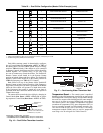
The maximum load allowed for the Chilled Water Pump
Starters is 5 VA sealed, 10 VA inrush at 24 volts. The starter
coil is powered from the chiller control system. The starter for
Chilled Water Pump 1 should be wired between LVT-25 and
LVT-21. The starter for Chilled Water Pump 2 should be wired
between LVT-24 and LVT-21. A field-installed chilled water
pump interlock for each pump must be connected to each
pump’s interlock points on the main base board. The chilled
water pump 1 interlock, CWP1, must be connected to MBB-
J7-1 and –2. The chilled water pump 2 interlock, CWP2, must
be connected to MBB-J7-3 and –4. The chilled water pump
interlock contacts should be rated for dry circuit application
capable of handling 5 vdc at 2 mA.
SINGLE INTEGRAL PUMP CONTROL — With a single
pump, the following options must be configured:
• Cooler Pump Control (Configuration
OPT1
CPC) =
ON.
• Cooler Pump 1 Enable (Configuration
OPT1
PM1E) = YES.
• Cooler Pump 2 Enable (Configuration
OPT1
PM2E) = NO.
With a single integral pump, the Cooler Pump Starter will
be energized when the machine is occupied. As part of the
factory-installed package, an auxiliary set of contacts is wired
to the MBB to serve as Chilled Water Pump Interlock. When
the mechanical cooling is called for, the pump interlock and
flow switch is checked. If the circuits are closed, the machine
starts its capacity routine. If the auxiliary contact interlock does
not close within 25 seconds of the ON command, a T190 —
Cooler Pump 1 Aux Contacts Failed to Close at Start-Up Alert
will be generated and the pump shut down. The unit will not
be allowed to start. If the chilled water flow switch does not
close within one (1) minute, two alarms will be generated. A
T192 — Cooler Pump 1 Failed to Provide Flow at Start-Up
Alert and an A200 — Cooler Flow/Interlock Failed to Close at
Start-Up Alarm will be generated and chiller will not be al-
lowed to start.
If the chilled water flow switch opens for at least 3 seconds
after initially being closed, a T196 — Flow Lost While Pump 1
Running Alert and an A201 — Cooler Flow/Interlock Contacts
Opened During Normal Operation Alarm will be generated
and the machine will stop.
If the control detects the chilled water pump interlock open
for 25 seconds after initially being closed, a T194 — Cooler
Pump 1 Contacts Opened During Normal Operation Alert is
generated and the unit is shut down.
If the control detects the chilled water flow switch circuit
closed for at least 5 minutes with the pump output OFF, an
A202 — Cooler Pump Interlock Closed When Pump is Off
Alarm will be generated and the unit will not be allowed to
start.
If the control detects that the chilled water pump auxiliary
contacts are closed for at least 25 seconds while the pump is
OFF, a T198 — Cooler Pump 1 Aux Contacts Closed While
Pump Off Alert is generated. The chiller will not be allowed to
start.
If the control starts a pump and the wrong interlock circuit
closes for at least 20 seconds, an A189 — Cooler Pump and
Aux Contact Input Miswire Alarm will be generated. The unit
will be prevented from starting.
As part of a pump maintenance routine, the pump can be
started to maintain lubrication of the pump seal. To utilize this
function, Cooler Pmp Periodic Start (Configuration
OPT1
PM.P.S) must be set to YES. This option is set to NO as the
factory default. With this feature enabled, if the pump is not op-
erating, it will be started and operated for 2 seconds starting at
14:00 hours. If the pump is operating, this routine is skipped. If
the pump has failed and an Alarm/Alert condition is active, the
pump will not start that day.
DUAL INTEGRAL PUMP CONTROL — With a dual inte-
gral pump package, the following options must be configured:
• Cooler Pump Control (Configuration
OPT1
CPC) =
ON.
• Cooler Pump 1 Enable (Configuration
OPT1
PM1E) = YES.
• Cooler Pump 2 Enable (Configuration
OPT1
PM2E) = YES.
Pump Start Selection is a field-configurable choice. Cooler
Pump Select (Configuration
OPT1
PM.SL) is factory
defaulted to 0 (Automatic). This value can be changed to 1
a30-4979