


59
selecting “YES”. This configuration menu also contains the
gains and minimum speed for the Motormaster control logic.
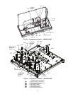
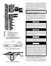
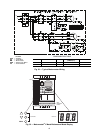
CONFIGURATION — The MMV is configured for 1 of 12
operation modes based on the inputs to the control terminal
block. The 30RAP units use operating modes 5-8. In these con-
figurations, the MMV follows a 4 to 20 mA speed reference
signal present on terminals 25 (+) and 2 (-). One additional
jumper is required to configure the drive for 50/60 Hz opera-
tion and input voltage. See Table 39 for proper inputs. Once the
drive is powered, it will change to the mode selected according
to the inputs. See Fig. 33.
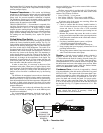
DRIVE PROGRAMMING
To enter password and change program values:
1. Press Mode.
2. Upper right decimal point blinks.
3. Display reads “00”. To enter the PROGRAM mode to ac-
cess the parameters, press the Mode button. This will ac-
tivate the PASSWORD prompt (if the password has not
been disabled). The display will read “00” and the upper
right-hand decimal point will be blinking. (See Fig. 33.)
4. Use the and buttons to scroll to the password
value (the factory default password is “1111”) and press
the Mode button. Once the correct password value is
entered, the display will read “P01”, which indicates that
the PROGRAM mode has been accessed at the beginning
of the parameter menu (P01 is the first parameter).
NOTE: If the display flashes “Er”, the password was incorrect,
and the process to enter the password must be repeated.
5. Press Mode to display present parameter number.
Upper right decimal point blinks.
Use the and buttons to scroll to the desired
parameter number.
Once the desired parameter number is found, press the
Mode button to display the present parameter setting. The up-
per right-hand decimal point will begin blinking, indicating
that the present parameter setting is being displayed, and that it
can be changed by using the up and down buttons. Use
and to change setting. Press Mode to store new setting.
Pressing the Mode will store the new setting and also exit
the PROGRAM mode. To change another parameter, press the
Mode key again to re-enter the PROGRAM mode (the param-
eter menu will be accessed at the parameter that was last
viewed or changed before exiting). If the Mode key is pressed
within two minutes of exiting the PROGRAM mode, the pass-
word is not required to access the parameters. After two min-
utes, the password must be entered in order to access the pa-
rameters again.
To change password: first enter the current password then
change parameter P44 to the desired password.
To disable automatic control mode and enter manual speed
control mode:
1. Change P05 to ‘01- keypad’.
2. Push UP and DOWN arrow key to set manual speed.
3. Set P05 to ‘04 - 4-20mA control’ to restore 4 to 20 mA
control.
EPM CHIP — The drive uses a electronic programming mod-
ule (EPM) chip to store the program parameters. This is an
EEPROM memory chip and is accessible from the front of the
VFD. It should not be removed with power applied to the
VFD.
LOSS OF CCN COMMUNICATIONS — Carrier Comfort
Network
®
(CCN) communications with external control
systems can be affected by high frequency electrical noise gen-
erated by the Motormaster V control. Ensure unit is well
grounded to eliminate ground currents along communication
lines.
If communications are lost only while Motormaster V con-
trol is in operation, order a signal isolator (CEAS420876-2)
and power supplies (CEAS221045-01, 2 required) for the CCN
communication line.
Fault Codes
— The drive is programmed to automatically re-
start after a fault and will attempt to restart three times after a
fault (the drive will not restart after CF, cF, GF, F1, F2-F9, or
Fo faults). If all three restart attempts are unsuccessful, the
drive will trip into FAULT LOCKOUT (LC), which requires a
manual reset.
Manual Reset
— If fault condition has been removed, cycle
power to the chiller to reset the VFD.
Troubleshooting
— Troubleshooting the Motormaster
®
V
control requires a combination of observing system operation
and VFD information. The drive provides 2 kinds of trouble-
shooting modes: a status matrix using the 3-digit display
(P57, P58) and real time monitoring of key inputs and outputs.
The collective group is displayed through parameters
50-60 and all values are read-only.
• P50: FAULT HISTORY — Last 8 faults
• P51: SOFTWARE version
• P52: DC BUS VOLTAGE — in percent of nominal.
Usually rated input voltage x 1.4
• P53: MOTOR VOLAGE — in percent of rated output
voltage
• P54: LOAD — in percent of drives rated output current
rating
• P55: VDC INPUT — in percent of maximum input:
100 will indicate full scale which is 5 v
• P56: 4-20 mA INPUT — in percent of maximum input.
20% = 4 mA, 100% = 20 mA
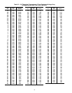
Manual Starter Trip
— If the VFD manual starter (MS-FC-
HS, MS-FC-A1 or MS-FC-B1 depending on model) trips,
locate the inrush current protectors (3 round black disks per
motor) and verify their resistance. For units operating at 208 v
or 230 v, these devices should measure approximately 7 ohms.
For all other voltages, they should measure approximately
20 ohms. Check value with mating plug disconnected, power
to chiller off and at ambient temperature (not hot immediately
after stopping VFD). These are standard resistances at 77 F
(25 C). Resistance values decrease at higher temperatures and
increase at lower temperatures.
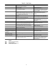
REPLACING DEFECTIVE MODULES — The Comfort-
Link
™
replacement modules are shown in Table 40. If the main
base board (MBB) has been replaced, verify that all configura-
tion data is correct. Follow the Configuration mode table and
verify that all items under sub-modes UNIT, OPT1 and OPT2
are correct. Any additional field-installed accessories or op-
tions (RSET, SLCT sub-modes) should also be verified as well
as any specific time and maintenance schedules.
Refer to the Start-Up Checklist for 30RAP Liquid Chillers
(completed at time of original start-up) found in the job folder.
This information is needed later in this procedure. If the check-
list does not exist, fill out the current information in the Config-
uration mode on a new checklist. Tailor the various options and
configurations as needed for this particular installation.
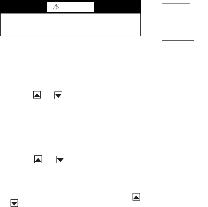
CAUTION
It is strongly recommended that the user NOT change any
programming without consulting Carrier service personnel.
Unit damage may occur from improper programming.