


52
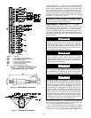
MINIMUM LOAD VALVE — On units equipped with the
factory-installed capacity reduction option, a solenoid valve
and discharge bypass valve (minimum load valve) are located
between the discharge line and the cooler entering-refrigerant
line. The MBB cycles the solenoid to perform minimum load
valve function and the discharge bypass valve modulates to the
suction pressure set point and the valve.
The amount of capacity reduction achieved by the mini-
mum load valve is not adjustable. The total unit capacity with
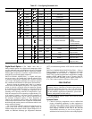
the minimum load valve is shown in Table 19.
PRESSURE RELIEF DEVICES — All units have one pres-
sure relief device per circuit located in the liquid line which re-
lieves at 210 F (100 C).
Check Unit Safeties
HIGH-PRESSURE SWITCH — A high-pressure switch is
provided to protect each compressor and refrigeration system
from unsafe high pressure conditions. See Table 32 for high-
pressure switch settings.
The high-pressure switch is mounted in the discharge line of
each circuit. If an unsafe, high-pressure condition should exist,
the switch opens and shuts off the affected circuit. The CSB
senses the compressor feedback signal and generates an appro-
priate alarm. The MBB prevents the circuit from restarting un-
til the alert condition is reset. The switch should open at the
pressure corresponding to the appropriate switch setting as
shown in Table 32.
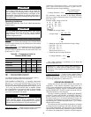
Table 32 — Factory Settings, High-Pressure
Switch (Fixed)
Clear the alarm using the scrolling marquee display as de-
scribed on page 63. The unit should restart after the compressor
anti-short-cycle delay, built into the unit control module,
expires.
PRESSURE TRANSDUCERS — Each refrigerant circuit is
equipped with a suction and discharge pressure transducer.
These inputs to the MBB are not only used to monitor the sta-
tus of the unit, but to also maintain operation of the chiller
within the compressor manufacturer's specified limits. The in-
put to the MBB from the suction pressure transducer is also
used to protect the compressor from operating at low pressure
conditions and low superheat conditions. In some cases, the
unit may not be able to run at full capacity. The control module
will automatically reduce the capacity of a circuit as needed to
maintain specified maximum/minimum operating pressures.
COOLER FREEZE-UP PROTECTION
The main base board (MBB) monitors leaving fluid temper-
ature at all times. The MBB will rapidly remove stages of ca-
pacity as necessary to prevent freezing conditions due to the
rapid loss of load or low cooler fluid flow.
When the cooler is exposed to lower ambient temperatures
(34 F [1° C] or below), freeze-up protection is required using
inhibited ethylene or propylene glycol.
HEATER CABLE — Optional factory-installed cooler and/or
hydronic package heaters are cycled based on the input from
the outside-air temperature sensor. These heaters, when in-
stalled, are designed to protect the cooler and/or hydronic pack-
age from freezing down to –20 F (–29 C). Power for these heat-
ers is supplied from the main unit power.
The input from the low pressure transducer provides a back-
up cooler freeze protection package. The MBB shuts down the
unit when a low pressure condition exists that could cause the
cooler to freeze up.
WINTER SHUTDOWN — At the end of the cooling season:
1. Drain the fluid from the cooler, hydronic package (if in-
stalled) and internal piping.
2. Fill the cooler and hydronic package with at least 2 gal-
lons (7.6 L) of inhibited propylene glycol or other suit-
able inhibited antifreeze solution to prevent any residual
water in the cooler and hydronic package/piping from
freezing.
3. At the beginning of the next cooling season, refill the
cooler and add the recommended inhibitor.
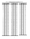
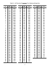
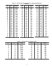
Thermistors — Electronic control uses up to five 5 k
thermistors to sense temperatures used to control operation of
the chiller. Thermistors EWT, LWT, RGTA, RGTB, and OAT
are identical in their temperature and voltage drop perfor-
mance. The SPT space temperature thermistor has a 10 k in-
put channel and it has a different set of temperature vs. resis-
tance and voltage drop performance. Resistance at various tem-
peratures are listed in Tables 33-37. For dual chiller operation,
a dual chiller sensor is required which is a 5 k thermistor.
When a digital compressor is used, a DTT (digital temperature
thermistor) is used. The DTT is an 86 k thermistor.
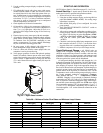
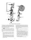
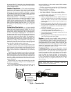
REPLACING THERMISTORS (EWT, LWT, RGT) — Add
a small amount of thermal conductive grease to the thermistor
well and end of probe. For all probes, tighten the retaining nut
¼ turn past finger tight. See Fig. 28.
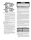
THERMISTOR/TEMPERATURE SENSOR CHECK — A
high quality digital volt-ohmmeter is required to perform this
check.
1. Connect the digital voltmeter across the appropriate the-
mistor terminals at the J8 terminal strip on the Main Base
Board (see Fig. 29).
2. Using the voltage reading obtained, read the sensor tem-
perature from Tables 33-37.
3. To check thermistor accuracy, measure temperature at
probe location with an accurate thermocouple-type tem-
perature measuring instrument. Insulate thermocouple to
avoid ambient temperatures from influencing reading.
Temperature measured by thermocouple and temperature
determined from thermistor voltage reading should be
close, ± 5° F (3° C) if care was taken in applying thermo-
couple and taking readings.
If a more accurate check is required, unit must be shut down
and thermistor removed and checked at a known temperature
(freezing point or boiling point of water) using either voltage
drop measured across thermistor at the J8 terminal, by deter-
mining the resistance with chiller shut down and thermistor
UNIT
CUTOUT CUT-IN
Psig kPa Psig kPa
30RA 650 4482 500 3447
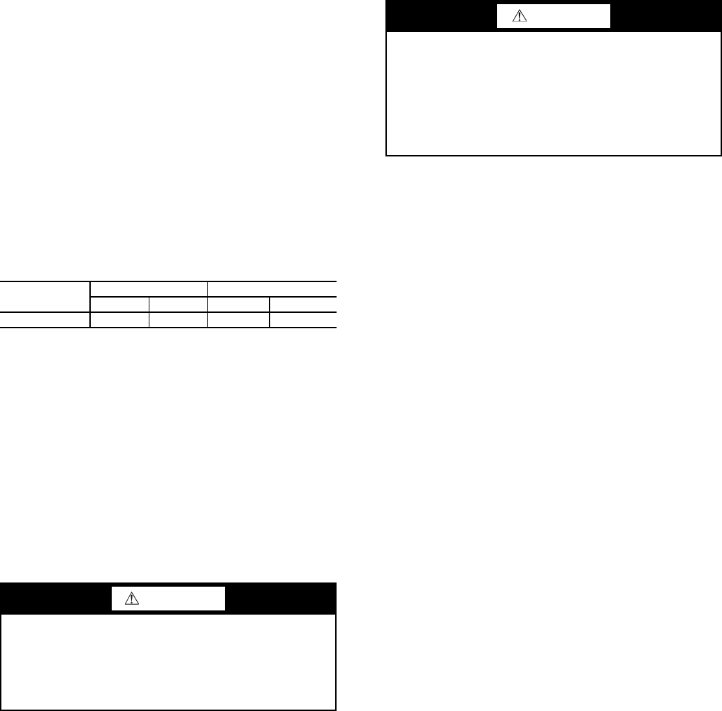
WARNING
On medium temperature brine units, the anti-freeze solu-
tion must be properly mixed to prevent freezing at a tem-
perature of at least 15 F (8.3 C) below the leaving-fluid
temperature set point. Failure to provide the proper anti-
freeze solution mixture is considered abuse and may impair
or otherwise negatively impact the Carrier warranty.
CAUTION
Do not disconnect main unit power when servicing com-
pressor(s) if ambient temperature is below 40 F (4.4 C).
The compressors have either a single circuit breaker or
multiple circuit breakers which can be used to shut off
power to the compressors. If power to the unit must be off
for a prolonged period, drain the cooler, hydronic package
(if installed) and internal piping. Add glycol according to
Winter Shutdown Step 2 below.