


49
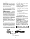
b. Place a digital voltmeter, on 20-volt AC scale,
across the black and white terminals on the con-
troller. Restore power to the controller. For at least
7 seconds, the voltmeter should read approxi-
mately 12 to 14 volts. Significant differences mean
the controller is defective or not properly config-
ured for the EXV valve.
c. Repeat the procedure in Step b above using the red
and green terminals on the controller. If the con-
troller responds properly, then the wiring may be
damaged or the valve may be plugged with debris
or otherwise obstructed.
d. The EXV valves on sizes 025, 030, 050-060 may
be disassembled for cleaning, inspection or motor
assembly replacement.
VALVE REPLACEMENT — The valve may be replaced by
unsoldering or cutting the piping. A tubing cutter must be used
to prevent creating contaminants in the piping.
VALVE REASSEMBLY — Perform the following procedure
to reassemble the EXV valve:
1. Use Service Test to open the EXV to 100%. This will re-
tract the white polyester driver/piston fully into the driver
guide. Remove power from the valve or controller.
2. Lightly oil the threads, and gasket or knife-edge on the
new motor adaptor. Carefully seat the adaptor on the
valve body or engage and tighten the lock nut if used.
Lock nuts should be torqued to approximately 45 ft-lb.
One eighth turn more than hand tight is sufficient to
achieve a leak proof seal on knife-edge joints.
3. After the motor is tightened, the cable should be replaced
on the valve. Care should be taken to ensure engagement
of the alignment key. Snap on the cable retainer.
4. Pressurize the system and check for leaks.
5. Reapply power to the ComfortLink™ controller. Since,
during service, valve position as calculated by the con-
troller will be lost, the controller should be initialized at
least twice. In some instances, cycling power to the con-
troller will accomplish this.
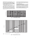
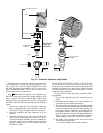
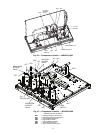
Compressor Replacement (Refer to Fig. 26
and 27) —
All models contain scroll compressors and have
from one to four compressors. The size 010-030 units are a sin-
gle refrigeration circuit while sizes 035-060 are dual circuit. A
compressor is most easily removed from the front of the unit,
depending on where clearance space was allowed during unit
installation.
Remove the junction box cover bolts and disconnect the
compressor power and ground connections. Remove the cable
from the compressor junction box. Remove the connections
from the high-pressure switch. Knock the same holes out of the
new compressor junction box and install the cable connectors
from the old compressor.
The compressors are bolted to rails, which are in turn bolted
to the unit basepan for all sizes except 010 and 015 which are
directly bolted to the basepan. Remove the 4 bolts holding the
compressor to the rail on the basepan. Save the mounting hard-
ware for use with the new compressor. Carefully cut the com-
pressor suction and discharge lines with a tubing cutter as close
to the compressor as feasible. Remove high-pressure switch
and pressure transducer(s) if required for compressor removal.
Lift one corner of the compressor at a time and remove all the
rubber mounting grommets (single compressor circuits) or
steel spacers (dual compressor circuits). Remove the old com-
pressor from the unit.
Slide the new compressor in place on the basepan. Lifting
one side of the compressor at a time, replace all of the compres-
sor mounting grommets. Using new tubing as required, recon-
nect compressor suction and discharge lines. Using hardware
saved, reinstall the mounting bolts and washers through the
compressor feet. Using proper techniques, braze suction and
discharge lines and check for leaks. Reconnect oil equalization
line on dual compressor circuit models.
Reconnect the compressor power connections and high-
pressure switch wiring as on the old compressor. Refer to
Fig. 26 and 27. Following the installation of the new compres-
sor, tighten all hardware to the following specifications. (See
Table 31.)
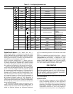
Table 31 — Unit Torque Specification
Cooler
BRAZED-PLATE COOLER HEAT EXCHANGER RE-
PLACEMENT — Brazed-plate heat exchangers cannot be
repaired if they develop a leak. If a leak (refrigerant or water)
develops, the heat exchanger must be replaced. To replace a
brazed-plate heat exchanger:
1. Check that the replacement heat exchanger is the same as
the original heat exchanger. The unit insulation covers the
manufacturer’s part number. Make sure the depths of the
replacement and original cooler heat exchangers are the
same.
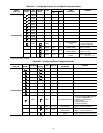
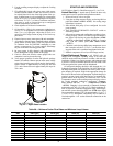
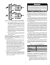
BLK
WHT
GRN
RED
BLK
WHT
GRN
RED
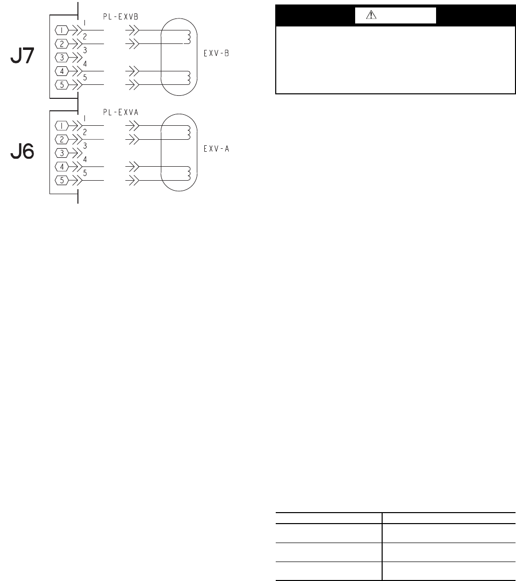
Fig. 25 — EXV Cable Connections to EXV Module
a30-4972
CAUTION
If the existing motor has been removed for inspection or
cleaning, be sure that the piston is fully retracted into the
motor assembly before installation on the valve. Failure to
do so will permanently damage the drive and motor.
Replacement motor assemblies are shipped in the retracted
position and may be installed as received.
FASTENER RECOMMENDED TORQUE
Compressor Mounting
Bolts
7 to 10 ft-lb (9.5 to 13.5 N-m)
Compressor Power
Connections
24 to 28 in.-lb (2.7- to 3.2 N-m)
Compressor Ground
Terminal Connections
14 to 18 in.-lb (1.6 to 2.0 N-m)