


30
LEAD/LAG DETERMINATION — This is a configurable
choice and is factory set to be automatic for all units unless the
unit is equipped with a digital scroll compressor or minimum
load, then circuit A is lead (Configuration
OPT2
LLCS).
The value can be changed to Circuit A or Circuit B leading as
desired. Set at automatic, the control will sum the current num-
ber of logged circuit starts and one-quarter of the current oper-
ating hours for each circuit. The circuit with the lowest sum is
started first. Changes to which circuit is the lead circuit and
which is the lag are also made when total machine capacity is
at 100% or when there is a change in the direction of capacity
(increase or decrease) and each circuit’s capacity is equal.
CAPACITY CONTROL OVERRIDES — The following over-
rides will modify the normal operation of the routine.
Deadband Multiplier
— The user configurable Deadband
Multiplier (Configuration
SLCT
Z.GN) has a default val-
ue of 1.0. The range is from 1.0 to 4.0. When set to other than
1.0, this factor is applied to the capacity Load/Unload Factor.
The larger this value is set, the longer the control will delay be-
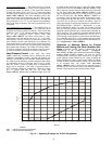
tween adding or removing stages of capacity. Figure 13 shows
how compressor starts can be reduced over time if the leaving
water temperature is allowed to drift a larger amount above and
below the set point. This value should be set in the range of 3.0
to 4.0 for systems with small loop volumes.
First Stage Override
— If the current capacity stage is zero,
the control will modify the routine with a 1.2 factor on adding
the first stage to reduce cycling. This factor is also applied
when the control is attempting to remove the last stage of
capacity.
Slow Change Override
— The control prevents the capacity
stages from being changed when the leaving fluid temperature
is close to the set point (within an adjustable deadband) and
moving towards the set point.
Ramp Loading
— Ramp loading (Configura-
tion
SLCT
CRMP) limits the rate of change of leaving
fluid temperature. If the unit is in a Cooling mode and config-
ured for Ramp Loading, the control makes 2 comparisons be-
fore deciding to change stages of capacity. The control calcu-
lates a temperature difference between the control point and
leaving fluid temperature. If the difference is greater than 4° F
(2.2° C) and the rate of change (°F or °C per minute) is more
than the configured Cooling Ramp Loading value (CRMP),
the control does not allow any changes to the current stage of
capacity.
Low Entering Fluid Temperature Unloading
— When the
entering fluid temperature is below the control point, the
control will attempt to remove 25% of the current stages being
used. If exactly 25% cannot be removed, the control removes
an amount greater than 25% but no more than necessary. The
lowest stage will not be removed.
Minimum Load Control
— If equipped, the minimum load
control valve is energized only when one compressor is run-
ning on circuit A. If the close control feature is enabled the
minimum load control valve may be used as needed to obtain
leaving fluid temperature close to set point.
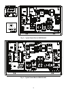
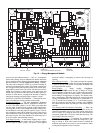
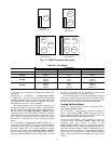
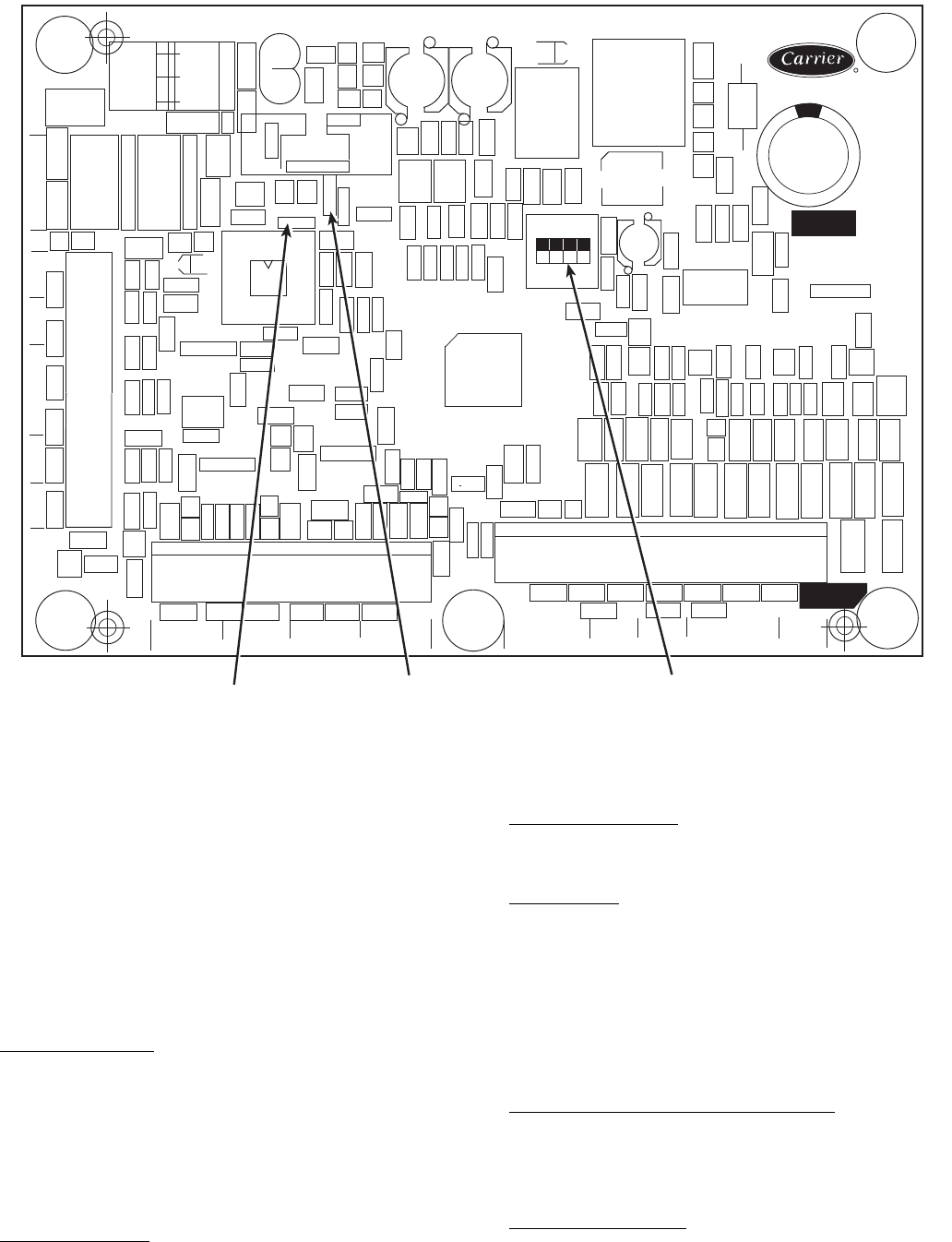
CEBD430351-0396-01C
TEST 1
CEPL130351-01
PWR
TEST 2
J1
J2
J4 J3
J5
J6
J7
LEN
STATUS
RED LED - STATUS
GREEN LED -
LEN (LOCAL EQUIPMENT NETWORK)
ADDRESS
DIP SWITCH
Fig. 12 — Energy Management Module