


58
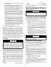
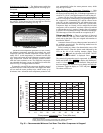
LOW SOUND FAN — A shroud and a wire guard provide
protection from the rotating fan. The exposed end of the fan
motor shaft is protected from weather by grease. If fan motor
must be removed for service or replacement, be sure to re-
grease fan shaft and reinstall fan guard. The fan motor has a
step in the motor shaft. For proper performance, fan should be
positioned such that it is securely seated on this step. Tighten
the bolt to 15 ± 1 ft-lb (20 ± 1.3 N·m).
Motormaster
®
V Controller — The Motormaster V
controller is standard on size 010 and 015 units. For other sizes,
the optional or accessory Motormaster V controller uses an in-
put signal from the AUX board. See Fig. 32. The controller is
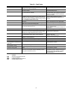
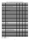
factory configured and requires no field programming. If a situ-
ation arises where the drive does not function properly, the in-
formation provided below and in Table 38 can be used to trou-
bleshoot the drive.
GENERAL OPERATION — The speed varies in proportion
to a 4 to 20 mA signal produced by the ComfortLink™ con-
trols. The MMV output speed is displayed in Hz.
The ComfortLink controls must be configured for MMV
operation in order for it to operate. This is configured under the
Configuration menu (Configuration
MM
MMR.S) and
26
25
24
23
22
17
16
15
14
13
12
11
10
9
8
7
6
3
1
3
1
3
1
6
2
4
2
4
2
12
11
21
20
19
18
10
9
8
7
6
5
4
5
4
3
2
1
4
2
1
3
5
J8
BLK
RED
LVT
4
3
22
23
T-55
ACCSY
SEN
OAT
BLU
BLU
BLK
RED
RGTB
BLK
RED
RGTA
SPTB
-
+
DPTB
-
+
A
C
B
A
C
B
GRN
RED
BLK
GRN
RED
BLK
SPTA
-
+
DPTA
-
+
A
C
B
A
C
B
GRN
RED
BLK
GRN
RED
BLK
BLK
RED
EVAPORATOR ENTERING
FLUID TEMP
BLK
RED
EVAPORATOR LEAVING
FLUID TEMP
SPACE TEMPERATURE
ACCESSORY OR
DUAL CHILLER LWT
J12 T55
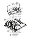
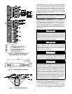
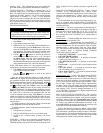
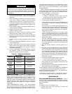
Fig. 29 — Thermistor Connections to
Main Base Board, J8 Connector
LEGEND
ACCSY — Accessory
DPT — Discharge Pressure Transducer
LWT — Leaving Water Temperature Sensor
LVT — Low Voltage Terminal
OAT — Outdoor Air Temperature Sensor
RGT — Return Gas Temperature Sensor
SEN — Sensor Terminal Block
SPT — Space Temperature Sensor
a30-4975
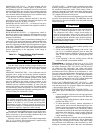
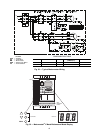
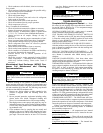
Fig. 30 — Chilled Water Flow Switch
a30-499
Fig. 31 — Mounted Fan Position
a30-4976
IMPORTANT: Check for proper fan rotation (counter-
clockwise when viewed from above). If necessary, switch
any 2 power leads to reverse fan rotation.
WARNING
Hazard of electrical shock. Wait three minutes after discon-
necting incoming power before servicing drive. Capacitors
retain charge after power is removed. Drive assembly
includes externally mounted current limiting resistors. Use
extreme caution when servicing the drive. Failure to com-
ply could result in possible personal injury.
WARNING
When configured as shown in this literature, this equip-
ment is designed to start when it receives line power.
Ensure that all personnel are clear of fans and guards are
installed before applying power. Failure to comply could
result in possible personal injury.
CAUTION
DO NOT connect incoming AC power to output terminals
T1, T2, and T3. Severe damage to the drive will result. Do
not continuously cycle input power to the drive more than
once every two minutes. Damage to the drive will result.
CAUTION
If input power has not been applied to the drive for a period
of time exceeding three years (due to storage, etc.), the
electrolytic DC bus capacitors within the drive can change
internally, resulting in excessive leakage current. This can
result in premature failure of the capacitors if the drive is
operated after such a long period of inactivity or storage. In
order to reform the capacitors and prepare the drive for
operation after a long period of inactivity, apply input
power to the drive for 8 hours prior to actually operating
the motor. Before attempting to operate the drive, motor,
and driven equipment, be sure all procedures pertaining to
installation and wiring have been properly followed. Fail-
ure to comply could result in equipment damage.