


43
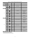
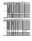
DEMAND LIMIT (CCN Loadshed Controlled) — To con-
figure Demand Limit for CCN Loadshed control set the De-
mand Limit Select (Configuration
RSET
DMDC) to 3.
Then configure the Loadshed Group Number (Configura-
tion
RSET
SHNM), Loadshed Demand Delta (Configu-
ration
RSET
SHDL), and Maximum Loadshed Time
(Configuration
RSET
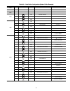
SHTM). See Table 27.
The Loadshed Group number is established by the CCN
system designer. The ComfortLink controls will respond to a
Redline command from the Loadshed control. When the
Redline command is received, the current stage of capacity is
set to the maximum stages available. Should the loadshed con-
trol send a Loadshed command, the ComfortLink controls will
reduce the current stages by the value entered for Loadshed
Demand delta. The Maximum Loadshed Time is the maximum
length of time that a loadshed condition is allowed to exist. The
control will disable the Redline/Loadshed command if no
Cancel command has been received within the configured
maximum loadshed time limit.
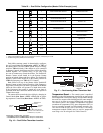
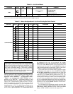
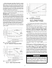
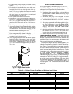
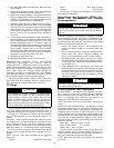
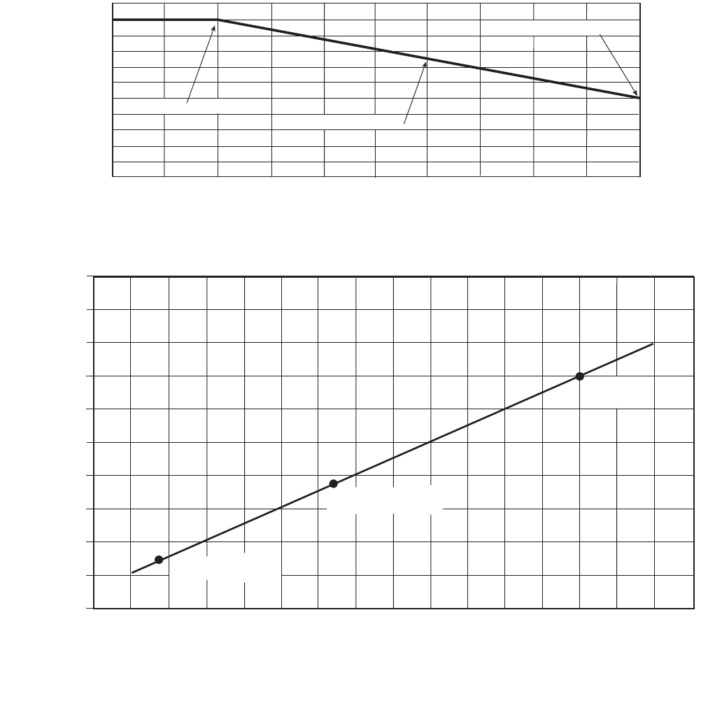
Cooling Set Point (4 to 20 mA) — A field supplied
and generated, externally powered 4 to 20 mA signal can be
used to provide the leaving fluid temperature set point. Connect
the signal to LVT7,8 (+,–). See Table 27 for instructions to
enable the function. Figure 22 shows how the 4 to 20 mA sig-
nal is linearly calculated on an overall 10 F to 80 F range for
fluid types (Configuration
OPT1
FLUD) 1 or 2. The set
point will be limited by the fluid (FLUD) type. Be sure that the
chilled water loop is protected at the lowest temperature.
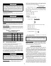
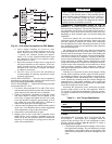
50% CAPACITY AT 20 mA
75% CAPACITY AT 12 mA
100% CAPACITY AT 4 mA
0
2
4
6
8
10
12
14
16 18
20
DEMAND LIMIT SIGNAL – 4 - 20 mA INPUT
100
80
60
40
20
0
MAX. ALLOWABLE LOAD (%)
Fig. 21 — 4 to 20-mA Demand Limiting
100
(38)
80
(27)
60
(15)
40
(4.4)
20
(-7)
0
(-17)
4 6.3 8.6 10.9 13.1 15.4 17.7 20
4 TO 20 mA SIGNAL TO EMM
SET POINT, F (C)
90
(32)
70
(21)
50
(10)
30
(-1)
10
(-12)
(FLUD = 2) MINIMUM
SET POINT 14 F (-10 C)
(FLUD = 1) MINIMUM
SET POINT 38 F (3.3 C)
MAXIMUM
SET POINT
70 F (21.1 C)
Fig. 22 — Cooling Set Point (4 to 20 mA)
EMM — Energy Management Module