


33
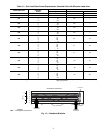
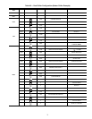
Table 20 — Fan Stages
Two other control methods are available for Machine On/
Off control:
OCCUPANCY SCHEDULE (Configuration
OPT2
CTRL = 2) — The main base board will use the operating
schedules as defined under the Time Clock mode in the scroll-
ing marquee display. These schedules are identical. The sched-
ule number must be set to 1 for local schedule.
The schedule number can be set anywhere from 65 to 99
for operation under a CCN global schedule. The Enable/Off/
Remote Contact must be in the Enable or Remote Contact posi-
tion. The control mode (Operating Modes
MODE) will be
1 when the switch is Off. The control mode will be 3 when the
Enable/Off/Remote Contact switch input is On and the time of
day is during an unoccupied period. Similarly, the control
mode will be 7 when the time of day is during an occupied
period.
CCN CONTROL (Configuration
OPT2
CTRL = 3) —
An external CCN device such as Chillervisor System Manager
controls the On/Off state of the machine. This CCN device
forces the variable ‘CHIL_S_S’ between Start/Stop to control
the chiller. The control mode (Operating Modes
MODE)
will be 1 when the switch is Off. The control mode will be 2
when the Enable/Off/Remote Contact switch input is On and
the CHIL_S_S variable is ‘Stop.’ Similarly, the control mode
will be 6 when the CHIL_S_S variable is ‘Start.’
Table 20 illustrates how the control method and cooling set
point select variables direct the operation of the chiller and the
set point to which it controls. The illustration also shows the
ON/OFF state of the machine for the given combinations.
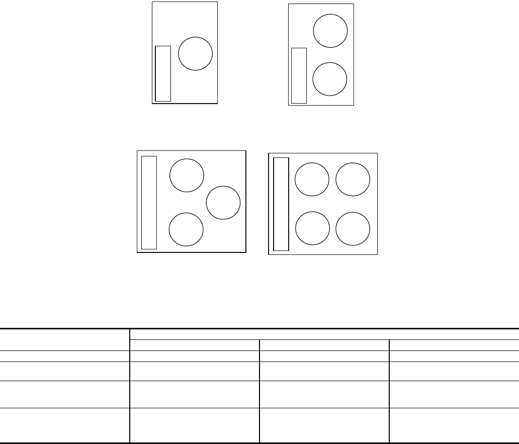
Cooling Set Point Select
SINGLE — Unit operation is based on Cooling Set Point 1
(Set Points
COOL
CSP.1).
DUAL SWITCH — Unit operation is based on Cooling Set
Point 1 (Set Points
COOL
CSP.1) when the Dual Set
Point switch contacts are open and Cooling Set Point 2 (Set
Points
COOL
CSP.2) when they are closed.
DUAL CCN OCCUPIED — Unit operation is based on
Cooling Set Point 1 (Set Points
COOL
CSP.1) during the
Occupied mode and Cooling Set Point 2 (Set
Points
COOL
CSP.2) during the Unoccupied mode as
configured under the local occupancy schedule accessible only
from CCN. Schedule Number in Table SCHEDOVR (See Ap-
pendix B) must be configured to 1. If the Schedule Number is
set to 0, the unit will operate in a continuous 24-hr Occupied
mode. Control method must be configured to 0 (switch). See
Table 21.
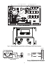
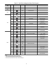
30RAP UNIT SIZE
FAN STAGES
Fan Stage Contactor Energized Fans Operating
010,015 Stage 1 — OFM1
018-030
Stage 1
Stage 2
FC1
FC1,2
OFM1
OFM1,2
035-050
Stage 1
Stage 2
Stage 3
FC1
FC2
FC1,2
OFM3
OFM1,2
OFM1,2,3
055,060
Stage 1
Stage 2
Stage 3
Stage 4
FC3
FC1,3
FC3,2
FC1,2,3
OFM4
OFM4,3
OFM4,1,2
OFM1,2,3,4
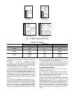
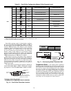
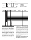
Top View
Top View Top View
Sizes 010,015
Sizes 035-050 Sizes 055,060
CONTROL BOX
CONTROL BOX
CONTROL BOX
OFM1
OFM2
OFM3
OFM3
OFM4
OFM2
OFM1
OFM1
Top View
Sizes 018-030
CONTROL BOX
OFM1
OFM2
Fig. 15 — 30RAP Condenser Fan Layout
a30-4970