


46
Operating Limitations
TEMPERATURES (See Table 29 for 30RAP standard tem-
perature limits).
High Cooler Leaving Chilled Water (Fluid) Temperatures
(LCWT) — During start-up with cooler LCWT above approx-
imately 60 F (16 C), the unit expansion valve will limit suction
pressure to approximately 90 psig (620 kPa) to avoid overload-
ing the compressor.
Low Cooler LCWT
— For standard units, the LCWT must be
no lower than 40 F (4.4 C). If the unit is the factory-installed
optional medium temperature brine unit, the cooler LCWT can
go down to 15 F (–9.4 C).
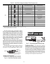
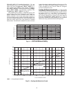
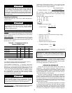
Table 29 — Temperature Limits for
Standard 30RAP Units
LEGEND
*For sustained operation, EWT should not exceed 85 F (29.4 C).
†Unit requires modification below this temperature.
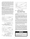
LOW-AMBIENT OPERATION — If operating temperatures
below 45 F (7 C) on size 018-030 units, and 32 F (0° C) on size
035-060 units are expected, accessory Motormaster® V con-
trol must be installed. Operating temperatures can go as low as
–20 F (–29 C) on size 010 and 015 units, as standard. Installa-
tion of wind baffles is also required. Refer to separate installa-
tion instructions for operation using this accessory. Contact
your Carrier representative for details.
VOLTAGE — ALL UNITS
Main Power Supply
— Minimum and maximum acceptable
supply voltages are listed in the Installation Instructions.
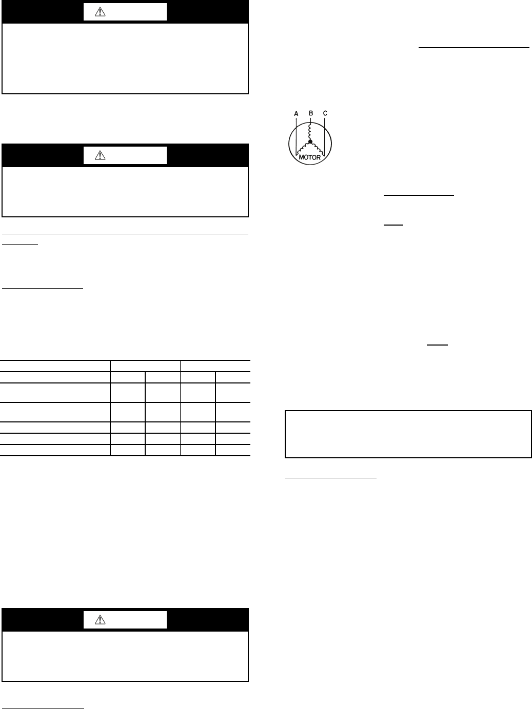
Unbalanced 3-Phase Supply Voltage — Never operate a motor
where a phase imbalance between phases is greater than 2%.
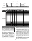
To determine percent voltage imbalance:
The maximum voltage deviation is the largest difference
between a voltage measurement across 2 legs and the average
across all 3 legs.
Example: Supply voltage is 240-3-60.
AB = 243 v
BC = 236 v
AC = 238 v
1. Determine average voltage:
2. Determine maximum deviation from average voltage:
(AB) 243 – 239 = 4 v
(BC) 239 – 236 = 3 v
(AC) 239 – 238 = 1 v
Maximum deviation is 4 v.
3. Determine percent voltage imbalance:
This voltage imbalance is satisfactory as it is below the
maximum allowable of 2%.
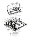
Control Circuit Power
— Power for the control circuit is
supplied from the main incoming power through a factory-
installed control power transformer (TRAN1) for all models.
Field wiring connections are made to the LVT.
OPERATION SEQUENCE
During unit off cycle, the control monitors the outdoor air
temperature. If the ambient temperature drops below 40 F
(4.4 C), cooler and hydronic system heaters (if either are facto-
ry installed) are energized. If power is maintained to the chiller
and the EMERGENCY ON/OFF switch is left in the OFF po-
sition, these heaters are also energized.
The unit is started by putting the ENABLE/OFF/REMOTE
CONTACT switch in the ENABLE or REMOTE CONTACT
position. When the unit receives a call for cooling (either from
the internal control or CCN network command or remote con-
tact closure), the unit stages up in capacity to maintain the leav-
ing fluid set point. The first compressor starts 1
1
/
2
to 3 minutes
after the call for cooling.
The lead circuit can be specifically designated on all models
or selected based on compressor run hours and starts depend-
ing on field configuration. The unit control will override this
selection under certain starting conditions to properly maintain
oil return to the compressors. In general, on dual compressor
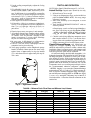
CAUTION
Never charge liquid into low-pressure side of system. Do
not overcharge. Overcharging results in higher discharge
pressure, possible compressor damage, and higher power
consumption. During charging or removal of refrigerant, be
sure water is continuously circulating through the cooler to
prevent freezing.
CAUTION
Do not operate with cooler leaving chiller water (fluid)
temperature (LCWT) below 40 F (4.4 C) for the standard
units, or below 15 F (–9.4 C) for units factory built for
medium temperature brine.
UNIT SIZE 30RA 010-030 035-060
Temperature F C F C
Maximum Ambient
Temperature
120 49 120 49
Minimum Ambient
Temperature
457 320
Maximum Cooler EWT* 95 35 95 35
Maximum Cooler LWT 70 21 70 21
Minimum Cooler LWT† 40 4.4 40 4.4
EWT —
Entering Fluid (Water) Temperature
LWT —
Leaving Fluid (Water) Temperature
CAUTION
Brine duty application (below 40 F [4.4 C] LCWT) for
chiller normally requires factory modification. Contact
your Carrier representative for applicable LCWT range for
standard water-cooled chiller in a specific application.
% Voltage Imbalance = 100 x
max voltage deviation
from avg voltage
average voltage
Average voltage =
243 + 236 + 238
3
=
717
3
= 239
% Voltage Imbalance = 100 x
4
239
= 1.7%
IMPORTANT: If the supply voltage phase imbalance is
more than 2%, contact your local electric utility company
immediately. Do not operate unit until imbalance condition
is corrected.