


47
circuits, the control will most often start the A1 or B1 compres-
sor first, especially after long off periods. The MBB controls
fan stages to maintain the head pressure set point and will auto-
matically adjust unit capacity as required to keep compressors
from operating outside of the specified envelope. There are no
pumpout or pumpdown sequences on these chillers.
For all units, if temperature reset is being used, the unit con-
trols to a higher leaving-fluid temperature as the building load
reduces. If demand limit is used, the unit may temporarily be
unable to maintain the desired leaving-fluid temperature be-
cause of imposed power limitations.
SERVICE
Electronic Components
CONTROL COMPONENTS — Unit uses an advanced elec-
tronic control system that normally does not require service.
For details on controls refer to Operating Data section.
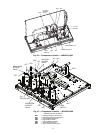
Access to the compressors is through latched panels from
beneath the control box on all models or from opposite the coil
side (sizes 010-030 only). The front door(s) provide access to
the compressor(s) and all components of the refrigeration sys-
tem. For size 010-030 units, access to the controls is through
the upper latched outer door above the compressor access door.
Similarly, the upper center latched door on sizes 035-060 gives
access to the controls. Inner panels are secured in place and
should not be removed unless all power to the chiller is off.
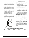
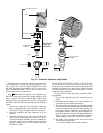
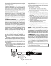
Electronic Expansion Valve (EXV) — See Fig. 24
for a cutaway view of the EXV. High-pressure liquid refriger-
ant enters valve through the top. As refrigerant passes through
the orifice, pressure drops and refrigerant changes to a 2-phase
condition (liquid and vapor). The electronic expansion valve
operates through an electronically controlled activation of a
stepper motor. The stepper motor stays in position, unless
power pulses initiate the two discrete sets of motor stator wind-
ings for rotation in either direction. The direction depends on
the phase relationship of the power pulses.
The motor directly operates the spindle, which has rotating
movements that are transformed into linear motion by the
transmission in the cage assembly. The valve includes a posi-
tive shut-off when closed.
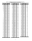
There are two different EXVs. See Table 30 for number of
steps. The EXV motor moves at 200 steps per second. Com-
manding the valve to either 0% or 100% will add extra steps to
the move, to ensure the value is open or closed completely.
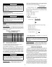
Table 30 — EXV Steps
The EXV board controls the valve. Each circuit has a
thermistor located in a well in the suction manifold before the
compressor. Suction pressure as measured by the suction pres-
sure transducer is converted to a saturated suction temperature.
The thermistor measures the temperature of the superheated
gas entering the compressor and the pressure transducer
determines the saturated temperature of suction gas. The differ-
ence between the temperature of the superheated gas and the
saturated suction temperature is the superheat. The EXV board
controls the position of the electronic expansion valve stepper
motor to maintain superheat set point.
The MBB controls the superheat leaving cooler to approxi-
mately 9° F (5° C). Because EXV status is communicated to
the main base board (MBB) and is controlled by the EXV
boards, it is possible to track the valve position. The unit is then
protected against loss of charge and a faulty valve. Just prior to
compressor start, the EXV will open. At low ambient tempera-
tures the EXV is closed at start up. After initialization period,
valve position is tracked by the EXV board by constantly mon-
itoring the amount of valve movement.
The EXV is also used to limit cooler saturated suction tem-
perature to 50 F (10 C). This makes it possible for the chiller to
start at higher cooler fluid temperatures without overloading
the compressor. This is commonly referred to as MOP (maxi-
mum operating pressure). At ambient temperatures above
110 F, MOP is bypassed at start-up to prevent charge backup in
the condenser.
If it appears that the EXV module is not properly control-
ling circuit operation to maintain correct superheat, there are a
number of checks that can be made using test functions and
initialization features built into the microprocessor control. See
the EXV Troubleshooting Procedure section to test EXVs.
EXV Troubleshooting Procedure — Follow steps
below to diagnose and correct EXV/economizer problems.
Check EXV motor operation first. Switch the Enable/Off/
Remote Contact (EOR) switch to the Off position. Press
on the Navigator™ display until ‘Select a menu item’ appears
on the display. Use the arrow keys to select the Service Test
mode. Press . The display will be:
> TEST OFF
OUTS
COMP
Press (password entry may be required) and use
to change ‘OFF’ to ‘ON’. Switch the EOR switch to
Enable. The Service Test mode is now enabled. Move the
pointer down to the OUTS sub-mode and press . Move the
pointer to item EXV.A or EXV.B as needed. Press and
the valve position will flash. Use to select 100% valve
position (hold for quick movement) and press .
The technician should be able to feel the actuator moving by
placing a hand on the EXV. A sight glass is located on the valve
body to verify that the sleeve is moving to expose/cover slots in
the orifice. A hard knocking should be felt from the actuator
when it reaches the top of its stroke (can be heard if surround-
ings are relatively quiet). Press again twice if necessary to
confirm this. To close the valve, press , select 0% with
and press . The actuator should knock when it reaches
the bottom of its stroke. If it is believed that the valve is not
working properly, continue with the checkout procedure
below:
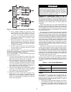
Check the EXV output signals at appropriate terminals on
the EXV module (see Fig. 25). Connect positive test lead to red
wire (EXV-J6 terminal 3 for Circuit A, EXV-J7 terminal 3 for
Circuit B). Set meter to approximately 20 vdc. Using the
Service Test procedure above, move the valve output under test
to 100%. DO NOT short meter leads together or pin 3 to any
other pin as board damage will occur.
WARNING
Electrical shock can cause personal injury and death. Shut
off all power to this equipment during service. There may
be more than one disconnect switch. Tag all disconnect
locations to alert others not to restore power until work is
completed.
UNIT SIZE 30RAP EXV STEPS
010-020 1596
025,030 2500
035-045 1596
050-060 2500
ESCAPE
ENTER
ENTER
ENTER
ENTER
ENTER
ENTER
ENTER
ENTER