


48
During the next several seconds, carefully connect the nega-
tive test lead to pins 1,2,4 and 5 in succession (plug J6 for Cir-
cuit A, plug J7 for Circuit B). Digital voltmeters will average
this signal and display approximately 6 vdc. If it remains con-
stant at a voltage other than 6 VDC or shows 0 volts, remove
the connector to the valve and recheck.
Press and select 0% to close the valve. Check the 4 po-
sition DIP switch on the board (all switches should be set to
On). If a problem still exists, replace the EXV module. If the
reading is correct, the expansion valve and EXV wiring should
be checked. Check the EXV terminal strip and interconnecting
wiring.
1. Check color coding and wire connections. Make sure
they are connected to the correct terminals at the EXV
driver and EXV plug and that the cables are not crossed.
2. Check for continuity and tight connection at all pin
terminals.
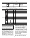
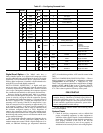
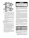
3. Check the resistance of the EXV motor windings. Re-
move the EXV module plug (J6 for Circuit A, J7 for Cir-
cuit B) and check the resistance of the two windings be-
tween pins 1 and 2 for one winding and pins 4 and 5 for
the other winding (see Fig. 25). The resistance should be
100 ohms ± 10 ohms.
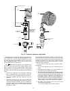
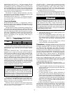
FIELD SERVICING INSTRUCTIONS — The EXV valves
on sizes 025, 030, 050-060 can be serviced. The EXV valves
on all other sizes are hermetic and cannot be disassembled for
installation or during service, however, the cable and retainer
may be replaced if necessary. Motor kits for the EXV valve are
available as replacement parts.
To remove the valve from the system, perform the follow-
ing procedure:
1. Be sure the refrigerant has been recovered from the
circuit.
2. Disconnect the line voltage to the valve controller. Dis-
connect the valve wires from the controller.
3. If the motor fails to operate properly, check the resistance
of each motor phase. Resistance between black and white
leads or between the red and green leads should be ap-
proximately 100 ohms. Differences of more than 10% be-
tween phases indicate a defective motor. Resistance be-
tween black and red, or any lead and piping, should be in-
finite or “open”. Any resistance reading will indicate a
shorted winding and the valve will need to be replaced.
4. The output of the controller to the valve can be tested
with the following procedure:
a. Disconnect supply voltage to the controller.
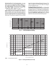
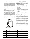
SPORLAN
MOTOR AND
ADAPTER
ASSEMBLY
CABLE
CABLE
CABLE RETAINER
CABLE
RETAINER
MOTOR ADAPTER
ASSEMBLY
MOTOR ADAPTER
ASSEMBLY
INCLUDED IN CABLE KIT
GASKET
SIGHTGLASS
FLOW
DIRECTION
NORMAL
FLOW
DIRECTION
Fig. 24 — Electronic Expansion Valve Details
a30-4971
ENTER